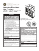
Lexington Direct Vent Gas Fireplace with the LexFire Burn System™ Models: LX32DV, LX36DV WARNINGS If the information in these instructions are not followed exactly, a fire or explosion may result causing property damage, personal injury or loss of life. – Do not store or use gasoline or other flammable vapors and liquids in the vicinity of this or any other appliance. – WHAT TO DO IF YOU SMELL GAS • Do not try to light any appliance.
CONTENTS LX Series Direct Vent Gas Fireplace The Lex-Fire Burn System sets a new standard for flame appearance through innovative log design, burner technology and ember placement. Each element affecting combustion and flame appearance was carefully scrutinized and strategically balanced during the design process. Important Safety Information.......................................3 Code Approval...............................................................4 Product Features..............................
IMPORTANT SAFETY INFORMATION LX Series Direct Vent Gas Fireplace INSTALLER OWNER Please leave these instructions with the appliance. Please retain these instructions for future reference. WARNING • Read this owner’s manual carefully and completely before trying to assemble, operate, or service this fireplace. • Any change to this fireplace or its controls can be dangerous.
IMPORTANT SAFETY INFORMATION LX Series Direct Vent Gas Fireplace IMPORTANT: PLEASE READ THE FOLLOWING CAREFULLY It is normal for fireplaces fabricated of steel to give off some expansion and/or contraction noises during the start up or cool down cycle. Similar noises are found with your furnace heat exchanger or car engine. IMPORTANT: PLEASE READ THE FOLLOWING CAREFULLY It is not unusual for gas fireplace to give off some odor the first time it is burned. This is due to the manufacturing process.
product features LX Series Direct Vent Gas Fireplace product SPECIFICATIONS • This appliance has been certified for use with • • • • • either natural or propane gas. See appropriate data plates. This appliance is not for use with solid fuels. The appliance is approved for bedroom or bedsitting room installations. The appliance must be installed in accordance with local codes if any. If none exist use the current installation code. ANSI Z223.1/NFPA 54 in the USA, CSA B149 in Canada.
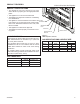
FIREPLACE and FRAMING DIMENSIONS LX Series Direct Vent Gas Fireplace Min. Rough Opening Depth 20 6QE” (516 mm) 10 6:O” (258 mm) 6 6 ” (168 mm) Dia. 4” (102 mm ) Dia. 21 6M” (553 mm) 21 6M” (553 mm) (7 31 92 6QE m ” m ) 4456M" (1124 mm) 1656O” (420 mm) m m ) 41556QE” (1059 mm) Min. Rough Opening Width ”( 15 88 Min.
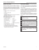
INSTALLATION INFORMATION LX Series Direct Vent Gas Fireplace Before You Start FIREPLACE FRAMING Read this homeowner manual thoroughly and follow all instructions carefully. Inspect all contents for shipping damage and immediately inform your dealer if any damage is found. Do not install any unit with damaged, incomplete, or substitute parts. Check your packing list to verify that all listed parts have been received.
INSTALLATION INFORMATION LX Series Direct Vent Gas Fireplace Fireplace Location Plan for the installation of your appliance. This includes determining where the unit is to be installed, the vent configuration to be used, framing and finishing details, and whether any optional accessories (i.e. blower, wall switch, or remote control) are desired. Consult your local building code agency to ensure compliance with local codes, including permits and inspections.
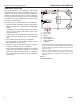
CLEARANCES LX Series Direct Vent Gas Fireplace WARNING Clearances to combustibles Follow these instructions carefully to ensure safe installation. Failure to follow instructions exactly can create a fire hazard. The appliance cannot be installed on a carpet, tile or other combustible material other than wood flooring. If installed on carpet or vinyl flooring, the appliance shall be installed on a metal, wood or noncombustible material panel extending full width and depth of the appliance.
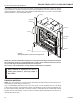
SECURE FIREPLACE to floor or framing LX Series Direct Vent Gas Fireplace The fireplace must be secured to the floor and/or to framing studs as shown in Figure 6. Use two (2) wood screws or masonry/ concrete screws to secure fireplace to the floor. Use four (4) screws to attach fireplace to framing. The side brackets are adjustable from 1/2" to 5/8" to accommodate different thickness of noncombustible material.
WARNING venting installation LX Series Direct Vent Gas Fireplace After conversion to top vent configuration the 4" (102 mm) flue pipe should be concentric within the 6B\," (175 mm) outer collar (within 1/4"). Flue Cover Screws Optional top vent application The appliance is shipped as a rear vent unit. If the installation layout requires the unit to be a top vent configuration the appliance can be converted by the following steps.
VENTING INSTALLATION Failure to follow these instructions will void the warranty. COMBUSTIBLE CLEARANCES FOR VENT PIPE WARNING WARNING Read all instructions completely and thoroughly before attempting installation. Failure to do so could result in serious injury, property damage or loss of life. Operation of improperly installed and maintained venting system could result in serious injury, property damage or loss of life.
VENTING INSTALLATION It is important to select the proper length of vent pipe for the type of termination you choose. It is also important to note the wall thickness. for horizontal termination Select the amount of vertical rise desired. All horizontal run of venting must have minimum 1/4" rise for every 12" of run towards the termination. You may use up to three 90° elbows in this vent configuration. Refer to Horizontal (Through the Wall) Termination Configurations on Page 18.
VENTING INSTALLATION LX Series Direct Vent Gas Fireplace General Venting Information - Termination Location INSIDE CORNER DETAIL V G H A D L V E C B V F Figure 11 Horizontal Vent Termination Locations B Fixed Closed Ope rable V B B V B V VENT TERMINATION V J A CFM145a V Fixed Closed Operable X AIR SUPPLY INLET X B M I V K X AREA WHERE TERMINAL IS NOT PERMITTED Canadian Installations1 US Installations2 CFM145a A = Clearance above grade, veranda, porch, 12” (30 cm)DV Ter
VENTING INSTALLATION LX Series Direct Vent Gas Fireplace Termination Clearances Termination clearances for buildings with combustible and noncombustible exteriors. Alcove Applications* Inside Corner Outside Corner G= Combustible 6" (152 mm) G V Noncombustible 2" (51 mm) V F= Combustible 6" (152 mm) Noncombustible 2" (51 mm) F Balcony with perpendicular side wall Balcony with no side wall D C C V E O E = Min. 2” (51 mm) for non-vinyl sidewalls Min.
VENTING INSTALLATION LX Series Direct Vent Gas Fireplace Rear Wall Vent installation When installed as a rear vent unit this appliance may be vented directly to a termination located on the rear outside termination behind the appliance • 45° elbows may only be attached to rear when used to • direct the flue skyward (to achieve additional rise). Do not attach 45° elbows to rear of appliance in which the flue turns either left or right and terminates horizontal.
VENTING INSTALLATION LX Series Direct Vent Gas Fireplace Deflecting Shield Interior Wall Surface Vent Cap (Horizontal Termination) Fire Stop Assembly Vent Cap T HO FP1957 FP2715 Screw Wood Screw Figure 17 Installing Horizontal Vent Cap For vinyl siding, stucco, or wood exterior use vinyl siding FP2715 standoffs between vent cap and exterior wall. The vinyl horiz cap w heat shield siding standoff prevents excessive from melting the vinyl siding material. Bolt the vent cap to the standoff.
VENTING INSTALLATION LX Series Direct Vent Gas Fireplace 3 x 90° Elbows B: 7’ A: 10’ 3 x 90° Elbows Horizontal 90° Elbow = 3' Reduction A + B = 17' Maximum 7’6” Figure 20 Maximum Three (3) 90° Elbows Per Installation Figure 22 Maximum Vent Run with Elbows FP1176 90° FP1959 36" (914 mm) Max. A FP1176 max 90 bends 36" (914 mm) Max. Figure 21 Maximum Horizontal Run with No Rise FP1959 max run w/elbows 7’6” (2.
VENTING INSTALLATION LX Series Direct Vent Gas Fireplace Below Grade Installations When it is not possible to meet the required vent terminal clearances of 12" above grade level, a snorkel kit is recommended. It allows installation depth down to 7" (178 mm) below grade level. The 7" (178 mm) is measured from the center of the horizontal vent pipe as it penetrates through the wall. If the foundation is recessed, use recess brackets (not supplied) for securing lower portion of the snorkel.
VENTING INSTALLATION LX Series Direct Vent Gas Fireplace INSTALLATION FOR VERTICAL TERMINATION 40' Maximum Height 8' Minimum Height 1. Determine the route your vertical venting will take. If ceiling joist, roof rafters or other framing will obstruct the venting system, consider an offset. Figure 29 to avoid cutting load bearing members.
VENTING INSTALLATION LX Series Direct Vent Gas Fireplace side. This prevents loose insulation from falling into the required clearance space. Figure 30. Otherwise, install firestop below the framed hole. The firestop should be installed with no less than three nails per side. Figure 35. Nails FP1969 Firestop Figure 30 If area above is a room, install firestop above framed hole as shown 1 2" 9/ 9 1/ 2 4. Connect a section of pipe and extend up through the hole.
fireplace installation LX Series Direct Vent Gas Fireplace check gas type Use proper gas type for the fireplace you are installing. If you have conflicting gas type, do not install fireplace. See dealer where you purchased the fireplace for proper fireplace according to your gas type. A qualified installer or service person must connect appliance to gas supply. Follow all local codes.
LX Series Direct Vent Gas Fireplace Only persons licensed to work with gas piping may make the necessary gas connections to this appliance. CAUTION WARNING fireplace installation A manual shutoff valve must be installed upstream of the appliance. Union tee and plugged 1/8" NPT pressure tapping point should be installed upstream of the appliance. Figure 34 A listed manual shutoff valve must be installed upstream of the appliance.
LX Series Direct Vent Gas Fireplace CHECKING GAS PRESSURE and ELECTRICAL INSTALLATION WARNING Do not use open flame to check for gas Millivolt gas valve leaks. CAUTION 1. Check gas type. The gas supply must be the same as stated on the appliance’s rating decal. If the gas supply is different from the fireplace, STOP! Do not install the appliance. Contact your dealer immediately. 2. To ease installation, a 30" (mm) flex line with manual shut-off valve has been provided with on this appliance.
Electrical installation LX Series Direct Vent Gas Fireplace Remote Wall mounted Switch A remote wall switch and up to fifteen (15) feet of 18 Ga. wire may be used with this appliance. Attach the wall switch in a junction box at the desired location on the wall. Figure 36. Do not extend beyond the wall switch wire length provided. NOTE: Extended lengths of wire may cause the fireplace not to function properly. Longer length of wire is permitted if the wire is made out of larger gauge (diameter) wire.
FINAL INSTALLATION LX Series Direct Vent Gas Fireplace 1. Release two clamps on bottom of fireplace. Figure 37 2. Tilt glass frame out and lift glass frame up until it clears three tabs on top of fireplace. 3. Set glass frame aside. CAUTION Glass Frame Removal Each clamp has a quick spring force. When reinstalling clamps, keep fingers clear. Glass Frame OF F Clamps Figure 37 Remove Glass Frame ! WARNING Three Tabs FP2718 remove glass frame HOT GLASS WILL CAUSE BURNS.
LOG PLACEMENT LX Series Direct Vent Gas Fireplace WARNING Before you begin — This unit is supplied with eight ceramic fiber logs. Do not handle these logs with your bare hands. Always wear gloves to prevent skin irritation from ceramic fibers. After handling the logs, wash your hands gently with soap and water to remove any traces of fibers. The positioning of the logs is critical to the safe and clean operation of this heater.
LOG PLACEMENT LX Series Direct Vent Gas Fireplace Rear Log #1 4. Place rear log (#1) on two pins against back side of firebox. Figure 39 Figure 39 Bottom Left Log #2 LG804 LG804 5. Place bottom left log (#2) on two pins LXagainst rear logleft side of firebox. Figure 40 Figure 40 LG803 LG803 LX left rear log Left Mid Log #6 6. Place left mid log (#6) on two left pins on burner assembly.
LOG PLACEMENT LX Series Direct Vent Gas Fireplace 7. Place right mid log (#7) on two right pins on burner assembly. Figure 42 Right Mid Log #7 Top Left Log #4 Figure 42 LG809 8. Place top left log (#4) on two pins on left mid log. Figure 43 LG809 LX right mid log LG806 Figure 43 Right Top Log #5 LG806 Topright left log 9. LX Place top log (#5) on two pins on middle left log.
LOG PLACEMENT LX Series Direct Vent Gas Fireplace 10. Place top center log (#8) across rear log (#1) pin and left mid log (#6) pin. Figure 45 Center Log #8 Figure 45 LG806 LG807 LX top log Air Space Under Rear Log Rockwool Figure 46 Rockwool 11. Break up rock wool (ember material) into dimesized pieces. Place evenly across both burner surfaces. Figure 46. LG811 Do not exceed 1/2" depth of coverage. For best flame and glow, do not LX rockwool block air space between burners and logs with rock wool.
AIR RESTRICTOR ADJUSTMENT LX Series Direct Vent Gas Fireplace Bend Tabs Up for All Vertical Applications Only Air Restrictor Slide Left and Right FP2719 Figure 47 Adjust Baffle on Air Restrictor Plate Screw The fireplace is equipped with a restrictorFP2719 plate that is located inside the top chamber of the fireplace. LxDepending air restrictor Venting Height (feet) upon the vent configuration, you may be required to adjust 8 to 20 the restrictor position 20 to 30 1. Remove glass frame.
FACING INSTALLATION notice LX Series Direct Vent Gas Fireplace Your firescreen’s finish has been covered at the factory with a protective enamel coating and should never be polished, nor should it ever need to be polished. Instead of polishing, clean with a mild soap solution using a clean cotton terry cloth, then dry. To remove any stubborn stains from the glass, use a mild soap solution, followed by a dampened towel (dampened with clean water only), followed by a dry towel without using soap.
OPERATING INSTRUCTIONS LX Series Direct Vent Gas Fireplace WARNING for your safety read before lighting If you do not follow these instruction exactly, a fire or explosion may result causing property damage, personal injury or loss of life. A. This appliance is equipped with a pilot which must be lit with built-in ignitor while following these instructions exactly. B. BEFORE OPERATING smell all around the appliance area for gas.
OPERATING INSTRUCTIONS LX Series Direct Vent Gas Fireplace approved leak testing method You may check for gas leaks with the following methods only: DANGER • Soap and water solution • An approved leak testing spray • Electronic sniffer WARNING Lighting pilot for the first time If using a soap and water solution to test for leaks, DO NOT spray solution onto control body. NOTE: Remove any excessive pipe compound from the connections. Excessive pipe compound can set off electronic sniffers.
OPERATING INSTRUCTIONS LX Series Direct Vent Gas Fireplace Lighting burner main burner switch The “ON/OFF/RS” switch for the main burner can be found behind door of the fireplace. This switch allows you to turn on and to turn off the main burner without using the gas valve knob. Make sure the button is in the “ON” position to light the main burner. Figure 50 ON OFF RS Lighting the burner Depress and turn the knob counterclockwise to the “ON” position. Figure 51.
cleaning and maintenance Make sure the gas valve knob is in the “OFF” position. Wait at least five (5) minutes before start-ing maintenance. Fireplace must be cold before starting maintenance. Venting system A qualified agency should examine the venting system annually. Cleaning glass Clean the ceramic glass periodically. Condensation will sometimes form on the glass during a cold startup. This is normal for all gas fireplaces. This condensation often attracts dust and lint to the surface of the glass.
LX Series Direct Vent Gas Fireplace Always use gloves when handling broken glass. WARNING CAUTION cleaning and maintenance Make sure the glass panel edges do not touch any metal parts during thermal expansion. • Never operate fireplace if glass is broken. • Replace any glass that is chipped, cracked, or broken. Replacement glass assemblies MUST be supplied by fireplace manufacturer — No substitute materials may be used.
TROUBLESHOOTING WARNING LX Series Direct Vent Gas Fireplace Turn appliance OFF and allow to cool before servicing. Only qualified service person should service and repair the heater. NOTE: All troubleshooting items are listed in order of operation. OBSERVED PROBLEM POSSIBLE CAUSE REMEDY Spark ignitor will not light the pilot after repeated pressing of spark ignitor. 1. Battery needs replacing 2. Defective ignitor 4. Bad wire. 1. Replace battery 2. Check connections to ignitor.
REPLACEMENT PARTS 4 LX Series Direct Vent Gas Fireplace 2 1 7 24 8 5 6 3 22 23 20 15 27 26 21 11 25 19 14 28 18 17 16 29 12 10 13 510528 LX parts 51D0528 WARNING LX36 9 LX32 9 Failure to position the parts in accordance with these diagrams or failure to use only parts specifically approved with this appliance may result in property damage or personal injury.
REPLACEMENT PARTS LX Series Direct Vent Gas Fireplace Ref. 1. 2. 3. 4. 5. 6. 7. 8. 9. 10. 11. 12. 13. 14. 15. 16. 17. 18. 19. 20. 21. 22. 23. 24. 25. 26. 27. 28. 29. Description Qty.
OPTIONAL ACCESSORIES LX Series Direct Vent Gas Fireplace Rolling "O" Decorative Arch Available in: Black, Textured Black, Vintage Iron, Gold Tone, Brushed Pewter and Gold Nantucket Decorative Arch Available in: Black, Textured Black, Vintage Iron, Gold Tone, Brushed Pewter and Gold Firescreen Doors Available in: Black, Textured Black, Vintage Iron, Gold Tone, Brushed Pewter and Gold 510528 LX trims 51D0528 41
LX Series Direct Vent Gas Fireplace OPTIONAL ACCESSORIES Decorative Fronts Description LX32 LX36 Black Rolling "O" Decorative Arched Facing LX32RBL LX36RBL Black Nantucket Decorative Arched Facing LX32NBL LX36NBL Rectangular Front Nantucket Black LX32RNBL LX36RNBL Textured Black Rolling "O" Decorative Arched Facing LX32RTB LX36RTB Textured Black Decorative Arched Facing LX32NTB LX36NTB Rectangular Front Nantucket Black LX32RNTB LX36RNTB Vintage Iron Rolling "O" Decorative Arched Facing LX32RVI LX36RVI
VENTING COMPONENTS LX Series Direct Vent Gas Fireplace 1 7 4 8 9 HO T 5 3 2 6 11 10 VENT COMPONENTS FOR 4" X 6B\," (Duravent, Selkirk) 4" x 6Z\x" (Metal-Fab) Current Old Duravent Duravent or Vermont or Vermont Qty./ Castings Group Castings Group Selkirk Metal-Fab Item Box Description Part no. Part no. Part no. Part no.
LX Series Direct Vent Gas Fireplace 44 51D0528
LX Series Direct Vent Gas Fireplace 51D0528 45
LX Series Direct Vent Gas Fireplace Massachusetts Residents Only — Please read and follow these special requirements NOTE REGARDING VENTED PRODUCTS This product must be installed by a licensed plumber or gas fitter when installed within the Commonwealth of Massachusetts. Any residence with a direct vent product must have a CO detector installed in the residence.
LX Series Direct Vent Gas Fireplace Limited lifetime warranty policy Lifetime Warranty The following components are warranted for life to the original owner, subject to proof of purchase: Firebox, Combustion Chamber, Heat Exchanger, Grate and Stainless Steel Burners. Five Year Warranty The following components are warranted five (5) years to the original owner, subject of proof of purchase: Ceramic Fiber Logs.
Based on CSA P.4.1-09 Efficiency Ratings Model EnerGuide Ratings Fireplace Efficiency (%) LX32DVN 65.1 LX32DVP 66.2 LX36DVN Recherchez dans la66.8 brochure LX36DVP les caractéristique de69.1 rendement énergétique de foyer au gaz Énerguide Based CSA P.4.1-09 Selonon CSA P.4.1-09 Vermont Castings Group 149 Cleveland Drive • Paris, Kentucky 40361 www.vermontcastingsgroup.