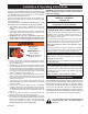
INSTALLER/CONSUMER SAFETY INFORMATION PLEASE READ THIS MANUAL BEFORE INSTALLING AND USING APPLIANCE WARNING! IF THE INFORMATION IN THIS MANUAL IS NOT FOLLOWED E X A C T LY, A F I R E O R EXPLOSION MAY RESULT CAUSING PROPERTY DAMAGE, PERSONAL INJURY OR LOSS OF LIFE. FOR YOUR SAFETY Installation and service must be performed by a qualified installer, service agency or the gas supplier.
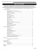
LHEDV Series Direct Vent Insert Table of Contents Please read the Installation & Operating Instructions before using this appliance. Thank you and congratulations on your purchase of an Vermont Castings Group fireplace insert. IMPORTANT - Read all instructions and warnings carefully before starting installation. Failure to follow these instructions may result in a possible fire hazard and will void the manufacturers' warranty. Installation Instruction General Information, Warnings, Cautions................
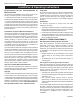
LHEDV Series Direct Vent Insert Installation & Operating Instructions This gas appliance should be installed by a qualified installer in accordance with local building codes and with current CSA-B149.1 Installation codes for Gas Burning Appliances and Equipment. ���� FOR U.S. Installations follow local codes and/or the current National Fuel Gas Code ANSI Z223.1/NFPA 54.
LHEDV Series Direct Vent Insert Installation & Operating Instructions Requirements for the Commonwealth of Massachusetts All gas fitting and installation of this heater shall only be done by a licensed gas fitter or licensed plumber.
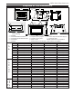
LHEDV Series Direct Vent Insert Fireplace & Trim Dimensions 3" (75mm) Dia.
LHEDV Series Direct Vent Insert Locating Your Gas Fireplace Insert with Zero Clearance Kit X A E B X For Zero Clearance Kit applications, it is important to determine the finished facing material before beginning to frame. This will allow for the thickness of the finishing material between the frame and the fireplace trim. Similarly, consideration must be given to the 1" inch depth of the air inlet channel sitting on the fireplace base.
LHEDV Series Direct Vent Insert Zero Clearance Applications An alternate air supply is recommended with this component. For installation other than in existing woodburning fireplaces such as new construction or renovation projects, a Zero Clearance Kit must be used. The kit enables these inserts to be installed in combustible environments. Whenever using a Zero Clearance Kit, consideration must be given to the dimensions of the Zero Clearance Kit and the requirements of the Air Kit.
LHEDV Series Direct Vent Insert The appliance, when installed must be electrically connected and grounded in accordance with local codes or, in the absence of local codes, with the current CSA C22.1 Canadian Electrical Code. The gas control is equipped with a captured screw type pressure test point, therefore it is not necessary to provide a 1/8" test point up stream of the control. When using copper or flex connector, use only approved fittings.
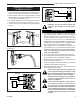
LHEDV Series Direct Vent Insert Honeywell Valve Right Side Installation Left Side Installation On/Off Switch Assembly On/Off Switch Assembly Wiring from Millivolt Gas Valve FP1330 Fig. 7 Insert ON/OFF switch with wiring assembly into bracket switch. FP1330 Switch assy 4/03 FP1331 Fig. 8 For left side installation, reverse switch position in bracket. SIT Valve THTP Thermopile FP1218 Fig. 9b On/Off switch wiring.
LHEDV Series Direct Vent Insert WARNING Some factory-built fireplaces have air passages on face of fireplace for zero clearance capabilities. Under no circumstances should these passages be blocked. Liner Installation The collar extending down from the termination base is the air intake connector. Be sure the flex vent, which is connected to this collar, is also connected to the labelled air intake flue collar on the fireplace.
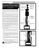
LHEDV Series Direct Vent Insert Flue gas exits through the vent termination rain cap Damper Outside combustion air enters through the lower level of the vent termination Secure with clamp and three screws 3" Flex Vent Two Pieces 1) Attach flexible pipe to rain cap 2) Secure with clamp 3) Attach raincap to vent termination using three screws Clamps & Screw Fastener Plate Pull flexible pipe through vent termination A or B Vent with 7" Inside Minimum and 14" Outside Maximum NOTE: Minimum Vent Height -
LHEDV Series Direct Vent Insert Round Vent Termination Installation Ceramic Refractory Installation Round Vent Termination Model HEDVRT is designed to be installed onto the LHECDV20, LHERDV20, LHECDV30 and LHERDV30 direct vent insert fireplaces. This round vent termination is built to be installed onto any type A-vent round chimney or B-vent round chimney. The minimum inside venting diameter must be at least 7" (178 mm) and the maximum outside diameter venting should not exceed 14" (356 mm). 1.
LHEDV Series Direct Vent Insert Venting Components 8" x 12" Vent Termination Kit Model: HEDVT (8" x 12" ) (Fit typical 8" x 12" and 9" x 13" flue tile) Kit Includes: A - 8" x 12" Vent Termination (x1) B - Stainless Steel Clamps (x4) C - Hardware Package (x1) B A C 12" x 12" Vent Termination Kit Model: HEDVT (12" x 12") (Fit typical 12"-13" x 12"-13" flue tile) Kit Includes: A - Vent Termination SL (x1) B - Stainless Steel Clamps 3"-3.
LHEDV Series Direct Vent Insert Operating Instructions General Glass Information Glass Frame Removal Only ceramic glass approved by Vermont Castings Group may be used for replacement on this unit. 1. The use of substitute glass will void all product warranties. 2. Care must be taken to avoid breakage of the glass. 3. Under no circumstances should this appliance be operated without glass properly installed, or with any cracked or broken glass.
LHEDV Series Direct Vent Insert d. Place the front right log (JR10). Position the Figure 22 log notch against the third grate from the right, LHECDV20 and LHERDV20 and the other edge of the log on top of the JR7 rear right log notch. Ensure the log is secure in place. e. Place the burner lava rock on the front area of the burner housing. (Fig. 22) LHECDV30, LHERDV30 (Fig. 23) a. Place the rear center log (KR24).
LHEDV Series Direct Vent Insert Flame Characteristics First Firing It is important to periodically perform a visual check of the pilot and the burner flames. Compare them to the Figure 26 and Figure 27 or 28. If any of the flames appear abnormal call a service person. Upon completing the gas line connection, a small amount of air will be in the lines. When first lighting unit with pilot light, it will take a few minutes to purge themselves of this air.
LHEDV Series Direct Vent Insert Lighting and Operating Instructions FOR YOUR SAFETY READ BEFORE LIGHTING WARNING: If you do not follow these instructions exactly, a fire or explosion may result causing property damage, personal injury or loss of life. A. This heater has a pilot which must be lit manually. When lighting the pilot follow these instructions exactly. B. BEFORE LIGHTING smell all around the heater area for gas.
LHEDV Series Direct Vent Insert Troubleshooting the Gas Control System SIT NOVA 820 Millivolt Valve NOTE: Before trouble shooting the gas control system, be sure external gas shut off is in the “On” position. WARNING: Before doing any gas control service work, remove glass front. SYMPTOM POSSIBLE CAUSES CORRECTIVE ACTION 1. Spark ignitor will not light A. Defective or misaligned Using a match, light pilot. If pilot lights, turn off electrode at pilot. pilot and push the red button again.
LHEDV Series Direct Vent Insert Troubleshooting the Gas Control System Honeywell Millivolt Valve START Gas Supply On CHECK NO Supply Line Hooked Up Shutoff Valve Open YES Pilot Lights With Piezo Ignitor NO YES Pilot Stays Lit NO Lockout Has Engaged. Wait 60 Seconds And Try Again. For Spark At Electrode While Depressing Piezo — 1/8" Gap To Pilot Hood Needed. All Wiring Connections Replace Piezo Ignitor For Air In The Lines Thermopile Needs A Minimum 325mv. Adjust Pilot Flame Height.
LHEDV Series Direct Vent Insert Instructions for RF Comfort Control Valve The Comfort Control Valve allows remote control of temperature, fan and flame appearance. NOTE: The antenna should hang in free air away from grounded metal. Operation 1. If the manual switch is in remote position, switch it to LOCAL. (Fig. 25) 2. Turn the pilotstat knob counterclockwise from OFF to the PILOT position, push the knob down, and hold in position. The pilot valve opens and allows gas to flow to the pilot burner. 3.
LHEDV Series Direct Vent Insert Delay Timer Mode Pilot Assembly The shut off delay timer has a maximum of 2 hours and a minimum of zero minutes. To change the timer level, press the time key followed by an arrow key. Pushing the key once will change the timer by 10 minutes. Fan Auto Mode In the AUTO mode, the room temperature, set temperature, flame and fan levels will be shown. AUTO will appear next to both the flame and fan icons.
LHEDV Series Direct Vent Insert 2. Slide the Remote/Local switch to REMOTE and teach the valve a transmitter (refer to Item 6, page 1). The Error Code will clear itself after approximately 1¹⁄₂ minutes and return to normal operation. LED Count 8 Service Action Replace valve 7 exists Confirm stepper motor connection 5 works Confirm fan connection exists and Auto Path If the manual switch is set to REMOTE, press the mode button to display AUTO on the transmitter.
LHEDV Series Direct Vent Insert Comfort Valve system control sequence of operation with transmitter Set manual switch to local or remote Five minute wait period Light pilot burner Did the LED stop blinking? No Review LED failure analysis Release pilotstat knob Yes Turn pilotstat knob from PILOT to ON Move switch from local to remote. Press any key on transmitter.
LHEDV Series Direct Vent Insert Maintenance Burner and Burner Compartment It is important to keep the burner and the burner compartment clean. At least once per year the logs and lava rock/ember material should be removed and the burner compartment vacuumed and wiped out. Remove and replace the logs as per the instructions in this manual. Always handle the logs with care as they are fragile and may also be hot if the fireplace has been in use. Fan Assembly The fan unit requires periodic cleaning.
LHEDV Series Direct Vent Insert LHERDV20/LHECDV20 10a/b 1b 4 2 1a 3 18 5 1e 16 14 1d 6a/b LHERDV30/LHECDV30 1c 18 17 8a/b 1b 1a 19 11a/b 7a/b 13a/b 9 a/b 1e 1d 20 15 21 22a/b 12a/b * 27 " * "/ " "/ 28/29 " 30 24a/b OT 23 a/b 26 OFF • 41 LE D REMOTE LOCAL ON • PIL 25 40 46 35 32 31 33 44 42 34 45 48 43 51 36 37 47 50 49 38 4894 Vermont Castings Group reserves the right to make changes in design, materials, specifications, prices
LHEDV Series Direct Vent Insert LHEDV Series (continued) Ref. Description LHERDV20 LHECDV20 LHERDV30 LHECDV30 1. Log Set Complete 10005332 10005332 10004866 10004866 1a. Log Rear Left 10005333 (JR7) 10005333 (JR7) 10004874 (KR22) 10004874 (KR22) 1b. Log Rear Right 10005334 (JR8) 10005334 (JR8) 10004875 (KR23) 10004875 (KR23) 1c. Log Rear Center 10004876 (KR24) 10004876 (KR24) 1d. Log Front Left 10005335 (JR9) 10005335 (JR9) 10004878 (KR25) 10004878 (KR25) 1e.
LHEDV Series Direct Vent Insert LHE Series (continued) Ref. Description LHER20 LHEC20 LHER30 LHEC30 37. Remote Switch (for RN or RP Units) 53606 53606 53606 53606 38. Remote Wire Harness w/Terminals (for RN or RP Units) 10002582 10002582 10002582 10002582 39. Ceramic Fiber Brick FP (Optional) JT1TR0 JT1TC0 KT1TR0 KT1TC0 40. Gasket Fan Cover 10003486 41. Flexible Connector (6") 10005098 10005098 10005098 10005098 42. Bracket Rear Log Assembly 10005370 10005369 10006771 10005489 43.
LHEDV Series Direct Vent Insert Optional Accessories Remote Controls Trim Options Optional remote control units are available to control different functions of the appliance. Face Kits Model RC1 RC2 IMTFK Function(s) Controlled ON/OFF ON/OFF and Temperature Wall mounted thermostat control NOTE: These remote controls are for RN/RP units only.
LHEDV Series Direct Vent Insert 10004894 29
LHEDV Series Direct Vent Insert 30 10004894
LHEDV Series Direct Vent Insert Limited lifetime warranty policy Lifetime Warranty The following components are warranted for life to the original owner, subject to proof of purchase: Firebox, Combustion Chamber, Heat Exchanger, Grate and Stainless Steel Burners. Five Year Warranty The following components are warranted five (5) years to the original owner, subject of proof of purchase: Ceramic Fiber Logs.
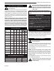
Efficiency Ratings Model LHECDV20RN LHECDV20RP LHECDV20RFN LHECDV30RFP LHERDV20RN LHERDV20RP LHECDV30RN LHECDV30RP LHECDV30RFN LHECDV30RFP LHERDV30RN LHERDV30RP EnerGuide Ratings Fireplace Efficiency (%) 61.3 61.3 61.3 61.3 59.7 59.7 61.5 61.5 61.5 61.5 64.1 64.1 Steady State (%) Fan-OFF Fan-ON 69 72 70 73 69 72 70 73 69 N/A 70 N/A 70 73 71 74 70 73 71 74 69 N/A 70 N/A Vermont Castings Group 149 Cleveland Drive • Paris, Kentucky 40361 www.vermontcastingsgroup.com D.O.E.