KSTDV Series Direct Vent Gas Fireplace Installation and Operating Instructions Model: KSTDV500(N/P)TSCSB WARNING: FIRE OR EXPLOSION HAZARD Failure to follow safety warnings exactly could result in serious injury, death or property damage. • • • Do not store or use gasoline or other flammable vapors and liquids in the vicinity of this or any other appliance. WHAT TO DO IF YOU SMELL GAS – Do not try to light any appliance. – Do not touch any electrical switch; do not use any phone in your building.
KSTDV Series Gas Fireplace CONTENTS Thank you and congratulations on your purchase of a Vermont Castings Group Fireplace! PLEASE READ THE INSTALLATION AND OPERATION INSTRUCTIONS BEFORE USING THE APPLIANCE! IMPORTANT: Read all instructions and warnings carefully before starting installation. Failure to follow these instructions may result in a possible fire hazard and will void the warranty. Important Safety Information ......................................3 Code Approval .................................
KSTDV Series Gas Fireplace IMPORTANT SAFETY INFORMATION INSTALLER OWNER Please leave these instructions with the appliance. Please retain these instructions for future reference. WARNING • Read this owner’s manual carefully and completely before trying to assemble, operate, or service this • • fireplace. Any change to this fireplace or its controls can be dangerous.
IMPORTANT SAFETY INFORMATION & CODE APPROVAL 15. This appliance, when installed, must be electrically grounded in accordance with local codes or in the absence of local codes, with the National Electrical Code, ANSI/NFPA 70, or the Canadian Electrical Code, CSA C22.1. 16. Do not obstruct the flow of combustion and ventilation air in any way. Provide adequate clearances around air openings into the combustion chamber along with adequate accessibility clearance for servicing and proper operation. 17.
KSTDV Series Gas Fireplace PRODUCT FEATURES PRODUCT SPECIFICATIONS • This appliance has been certified for use with either • • • • • • natural or propane gas. See appropriate data plates. This appliance is not for use with solid fuels. The appliance is approved for bedroom or bedsitting room installations. The appliance must be installed in accordance with local codes if any. If none exist use the current installation code. ANSI Z223.1/NFPA 54 in the USA, CSA B149 in Canada.
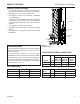
FIREPLACE & FRAMING DIMENSIONS KSTDV Series Gas Fireplace Rough Opening Depth 25” (635 mm) 1156O” (292 mm) 23” (584 mm) 1/2” or 5/8” Recessed Nailing Flange 50” (1270 mm) Rough Opening Width Rough Opening Height 456M” (108 mm) 44 6M” (1137 mm) 4456O” (1130 mm) 36” (914 mm) 39 6 ” (1007 mm) 30" 38 6 ” (762 mm) (981 mm) 24” (610 mm) 4956O” (1257 mm) Figure 2 Fireplace and Framing Dimensions NOTE: For exterior wall applications, outdoor facing kit KST500SSDK is required.
PRE-INSTALLATION INFORMATION KSTDV Series Gas Fireplace BEFORE YOU START FIREBOX FRAMING Read this homeowner manual thoroughly and follow all instructions carefully. Inspect all contents for shipping damage and immediately inform your dealer if any damage is found. Do not install any unit with damaged, incomplete, or substitute parts. Check your packing list to verify that all listed parts have been received.
PRE-INSTALLATION INFORMATION KSTDV Series Gas Fireplace • Vent pipe routing. See Venting section found in this FIREPLACE LOCATION Plan for the installation of your appliance. This includes determining where the unit is to be installed, the vent configuration to be used, framing and finishing details, and whether any optional accessories (i.e. blower, wall switch, or remote control) are desired.
KSTDV Series Gas Fireplace CLEARANCES CLEARANCES TO COMBUSTIBLES 12” WARNING Follow these instructions carefully to ensure safe installation. Failure to follow instructions exactly can create a fire hazard. The appliance cannot be installed on a carpet, tile or other combustible material other than wood flooring. If installed on carpet or vinyl flooring, the appliance shall be installed on a metal, wood or noncombustible material panel extending full width and depth of the appliance.
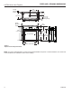
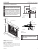
FIREPLACE INSTALLATION KSTDV Series Gas Fireplace SECURE FIREPLACE TO FLOOR OR FRAMING NOTE A 6" area above fireplace must be a noncombustible material. Figure 6 NOTE The fireplace must be secured to the floor and/or to framing studs as shown in Figure 6 . Use four (4) wood screws or masonry/ concrete screws to secure fireplace to the floor. Use four (4) screws to attach fireplace to framing. The side brackets or nailing flanges are designed to accommodate two wall boards thicknesses, 1/2" or 5/8".
KSTDV Series Gas Fireplace WARNING VENTING INSTALLATION Read all instructions completely and thoroughly before attempting installation. Failure to do so could result in serious injury, property damage or loss of life. Operation of improperly installed and maintained venting system could result in serious injury, property damage or loss of life. **1” *3” **1” 72” (1829 mm) 24” (610 mm) INSTALLATION PRECAUTIONS Consult local building codes before beginning the installation.
VENTING INSTALLATION • Horizontal Termination • Vertical Termination It is important to select the proper length of vent pipe for the type of termination you choose. It is also important to note the wall thickness. FOR HORIZONTAL TERMINATION Select the amount of vertical rise desired. All horizontal run of venting must have 1/4" rise for every 12" of run towards the termination below 71⁄2" of vertical rise from floor of fireplace.
VENTING INSTALLATION KSTDV Series Gas Fireplace TERMINATION LOCATION INSIDE CORNER DETAIL G V H A D V E L C B V F B Fixed Closed Ope rable V B V Operable V Fixed Closed B B B J V VENT TERMINATION M X I A CFM145a Figure 8 – Termination Locations V X AIR SUPPLY INLET V K X AREA WHERE TERMINAL IS NOT PERMITTED CANADIAN INSTALLATIONS1 US INSTALLATIONS2 A = Clearance above grade, veranda, porch, deck or balcony 12" (30cm) 12" (30cm) B = Clearance to window or door that may
VENTING INSTALLATION KSTDV Series Gas Fireplace TERMINATION CLEARANCES Termination clearances for buildings with combustible and non-combustible exteriors. Inside Corner Alcove Applications* Outside Corner D C G= Combustible 6" (152 mm) G V Noncombustible 2" (51 mm) V V M E = Min. 2” (51 mm) for non-vinyl sidewalls Min. 12” (305 mm) for vinyl sidewalls O = 8’ (2.4 m) Min. M V No. of Caps DMIN. CMAX.
VENTING INSTALLATION KSTDV Series Gas Fireplace VERTICAL SIDEWALL INSTALLATION NOTE: Sealant is not required to assemble fireplace venting. Do not use silicone sealant at the inner flue exhaust connections. Step 1 X Locate vent opening on the wall. It may be necessary to first position the fireplace and measure to obtain hole location. Depending on whether the wall is combustible or noncombustible, cut opening to size. Figure 11 (For combustible walls first frame in opening.
VENTING INSTALLATION KSTDV Series Gas Fireplace VERTICAL/HORIZONTAL TERMINATION CONFIGURATIONS Since it is very important that the venting system maintain its balance between the combustion air intake and the flue gas exhaust, certain limitations as to vent configurations apply and must be strictly adhered to. 24" (610 mm) Min. *NOTE: With a 24" rise, the horizontal run must be 36".
KSTDV Series Gas Fireplace VENTING INSTALLATION • For each 45° elbow installed in the horizontal run, the • length of the horizontal run MUST be reduced by 18" (457 mm). This does not apply if the 45° elbows are installed on the vertical part of the vent system. The maximum number of elbow degrees in a system is 270°. Figure 17 3. 4. 5. Elbow 1 Elbow 2 Elbow 3 Elbow 4 Total Angular Variation Example: = = = = = 6. 90° 45° 45° 90° 270° 7. supplied).
VENTING INSTALLATION WARNING KSTDV Series Gas Fireplace • Do not back fill around snorkel. • A clearance of at least 4" must be maintained between the snorkel and the soil. 40' (12 m) Maximum Height 12' (3.7 m) Minimum Height NOTICE VERTICAL THROUGH-THE-ROOF APPLICATIONS B A restrictor disc must be installed on vertical terminations that are higher than 12' (366 cm). A Install restrictor disc as shown in Figure 20 for vertically vented applications.
KSTDV Series Gas Fireplace VENTING INSTALLATION For optimal flame appearance, a restrictor disk is necessary on straight vertical runs of 10' of more. • Runs may not incorporate elbows. • The disk is part number 56D3027 and is included in 1 2 • 3 4 • 24" (610 mm) Min. Elbow 1 Elbow 2 Elbow 3 Elbow 4 Total Angular Variation Example: = = = = = 90° 45° 45° 90° 270° Figure 22 Maximum Elbow Usage INSTALLATION FOR VERTICAL TERMINATION 1. Determine the route your vertical venting will take.
VENTING INSTALLATION KSTDV Series Gas Fireplace /" 10 1 2 101 / 2 " FP1970 Firestop Nails Figure 25 If Area Above is Not a Room, Install Firestop above Framed Hole as Shown 2. Assemble the desired lengths of pipe and elbows necessary to reach from the burner system flue up through the firestop. Be sure pipe and elbow connections are fully twist-locked. 3. Cut a hole in the roof using the locating hole as a center point. (Cover any exposed open vent pipes before cutting hole in roof).
KSTDV Series Gas Fireplace GAS PIPE INSTALLATION CHECK GAS TYPE WARNING Use proper gas type for the fireplace you are installing. If you have conflicting gas type, do not install fireplace. See dealer where you purchased the fireplace for proper fireplace according to your gas type. External Regulator A qualified installer or service person must connect appliance to gas supply. Follow all local codes. 100 gal.
GAS PIPE INSTALLATION Apply pipe joint sealant lightly to male threads. This will prevent excess sealant from going into pipe. Excess sealant in pipe could result in clogged burner system valves. INSTALL GAS SUPPLY LINE NOTE : The gas line connection may be made using 1/2" rigid tubing or an approved flex connector. Since some municipalities have additional local codes it is always best to consult your local authorities and the current edition of the National Fuel Gas Code ANSI.Z223.1, NFPA54.
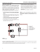
CHECKING GAS PRESSURE AND ELECTRICAL INSTALLATION KSTDV Series Gas Fireplace Pressure Inlet CHECK GAS PRESSURE 1. This fireplace is equipped with the Signature Control valve which operates on 6 volts. The AC module plugs into the fireplace junction box A/C power supply. Four (4) “AA” batteries are used for back up during power outages. 2. The Signature Command System can also be operated without A/C power. The system can run on four (4) “AA” batteries for approximately six (6) months under normal use. 3.
KSTDV Series Gas Fireplace CHECKING GAS PRESSURE AND ELECTRICAL INSTALLATION JUNCTION BOX WIRING COMMAND CENTER WALL INSTALLATION 1. This should be done before framing the fireplace. Wire the receptacle into an electrical circuit. Wire with minimum 60° C wire in accordance with prevailing codes. 2. Remove the external junction box cover by removing the screw from the side of the outside firebox wall. Junction box was installed at the factory. 3.
CHECKING GAS PRESSURE AND ELECTRICAL INSTALLATION KSTDV Series Gas Fireplace SIGNATURE COMMAND WIRING DIAGRAM Light 300 Watt Max A/C Module To Outlet Pilot Optional Blower 300 Watt Max Rear Burner Solenoid 300 Watt Max RF Receiver ON/OFF Button A/C Module Control Board Black / Thermopile Red / Thermopile Sensor Conversion NG/LP Ignitor / Sparker Plug-in Connector Control Board to Command Center OFF/LO NOTE: Wall switch wires must be connected together if a wall switch is not being used.
OPTIONAL FAN BLOWER SYSTEM The black and white wires on the AC box wiring harness are marked ‘Blower’, ‘Light’ and ‘Aux’. It is important to use the wires marked ‘Blower’ or the control will not work correctly. BLOTKSTSC SIGNATURE COMMAND BLOWER The BLOTKSTSC Blower Kit requires the SCSACM A/C Module and the TSFRSC remote to install and operate this kit. Refer to blower instructions for installation and remote instructions for operation.
KSTDV Series Gas Fireplace GLASS FRAME REMOVAL NOTE: You must first remove the safety barrier before you remove the glass frame. To remove the barrier, lift up and pull out until the tabs are clear of their corresponding slots on the firebox. Then proceed to remove the glass frame by: 1. Remove the plate located in front of the glass at the bottom. 2. Remove rod provided for screen assembly located beneath the cover plate. 3. Rotate the access doors on the right and left side of the glass toward the glass.
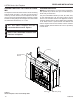
FINAL INSTALLATION KSTDV Series Gas Fireplace LIGHT & BRICK INSTALLATION 1. Remove glass frames from fireplace. 2. Remove the six (6) screws securing each light box and remove from unit. Figure 34 Bulb Socket 6. Place the floor brick panels on the brick supports between the hearth bricks. 7. Place the wall brick panels against the firebox walls, setting on the floor and hearth bricks. The wall brick will be held in place by the brick retainer tab on the light box cover. Figures 34 & 36 8.
KSTDV Series Gas Fireplace FINAL INSTALLATION LOG PLACEMENT 1. From the back side of the unit (with the controls on your left) and holding log #1 in your left hand with the widest end of the log away from you, place the log over the pilot, making sure to locate notches in log over the first tine from left on the near side and the first two tines from the left on the front side of the unit. tine from the left. Position log with the inside face of the log perpendicular to the middle burner.
FINAL INSTALLATION KSTDV Series Gas Fireplace 5. Move to the other side of the unit to place the remaining logs. 6. From the front of the unit (with the controls on your right) and hold log # 5 in your right hand with the knots at each end of the log facing you and the notched end on your left, place the log on the key on the top of log #1 with the notch in the bottom of the log resting on the front of the third tine from the right. 8.
KSTDV Series Gas Fireplace FINAL INSTALLATION DANGER CERTIFIED SAFETY BARRIER HOT GLASS WILL CAUSE BURNS. DO NOT TOUCH GLASS UNTIL COOLED. SAFETY BARRIER INSTALLATION INSTRUCTIONS NOTE: A barrier designed to reduce the risk of burns from the hot viewing glass is provided with this appliance and shall be installed for the protection of children and other at risk individuals. If the barrier becomes damaged, the barrier shall be replaced with the manufacturer's barrier for this appliance.
KSTDV Series Gas Fireplace OPERATING INSTRUCTIONS WARNING FOR YOUR SAFETY READ BEFORE LIGHTING If you do not follow these instructions exactly, a fire or explosion may result causing property damage, personal injury or loss of lie. A. This appliance is equipped with an ignition device which automatically lights the pilot. Refer to the instructions. B. BEFORE OPERATING smell all around the appliance area for gas.
KSTDV Series Gas Fireplace OPERATING INSTRUCTIONS OPERATING INSTRUCTIONS 1. STOP! Read the safety information above. 2. This appliance is equipped with an ignition device which automatically lights the burner. Do not try to light the burner by hand. 3. With five (5) minutes to clear out any gas. Then smell for gas, including near the floor. If you smell gas, STOP! Follow "B" in the safety information on page 32. If you do not smell gas, go to next step. 4. Press the master switch to the "ON" (-) position.
KSTDV Series Gas Fireplace SIGNATURE COMMAND SYSTEM OPERATION INSTRUCTIONS FEATURES RF Receiver ON/OFF Command Center To Thermopile To Sensor To Sparker • Easy Access Function Operation and System Configuration • Operation Confirmation/Fault Diagnostic Indications (LED/Buzzer) • ON/OFF/HI/Med/Low Operation • Optional Wall Mounting Control Board battery 6-hour Automatic Shut Down Option Convenient NG/LP Gas Type Conversion Standing Pilot/Intermittent pilot Conversion Previous settings Restoration Abil
SIGNATURE COMMAND SYSTEM OPERATION INSTRUCTIONS KSTDV Series Gas Fireplace Either mode benefits from the instantaneous battery backup, so you never have to worry about a power outage. NOTE: The Signature Command System comes standard in the Intermittent Pilot mode, so you must follow the instructions below to switch to Standing Pilot Mode if needed. Intermittent/Standing Pilot Setup (Default intermittent) 1.
KSTDV Series Gas Fireplace SIGNATURE COMMAND SYSTEM OPERATION INSTRUCTIONS FUNCTIONS/OPERATION (with Command Center) Turning on the fireplace 1. Turn on the master switch and wait for a beep. 2. Press the ON button on the Command Center or turn on wall switch. Pilot will light and burner will come on High setting or last memory setting (See Turning Off Fireplace below). For memory feature. Pilot Safety Lockout Function 1. If the pilot doesn’t light after sparking for 30 seconds, pilot trial lockout happens.
WARNING The information bar shows the room temperature, the “sending signal” radio icon, the low battery indication icon, the child-proof icon, and the flame icon. This area doesn’t have touch buttons. • The room temperature will always be shown after • power-up. It displays the room temperature from 40 °F to 99 °F. “Lo” and “HI” will be displayed when the room temperature is lower than 40°F or higher than 99°F, respectively. The radio icon will be shown when the transmitter is sending a signal.
KSTDV Series Gas Fireplace TOUCH SCREEN REMOTE CONTROL OPERATION Setting Privacy Code on Transmitter: Figure 50 Command Center ON LED The remote transmitter privacy code is preset in factory. In the event of activation or interference from other nearby transmissions, change the code using the following procedures (learn function must be performed after changing the code): Performing Learn Function 1.
TOUCH SCREEN REMOTE CONTROL OPERATION THERMO, LIGHT, FAN, AUX) are pressed and flashing. 1. Press the ON/up button to turn on the fireplace. The flame icon on the LCD displays High. 2. Press the OFF/down button to decrease the flame height and turn off the fireplace. When the OFF/down button is pressed for three times, the flame icon changes form High to Medium, to Low, then to Off. 3.
KSTDV Series Gas Fireplace TOUCH SCREEN REMOTE CONTROL OPERATION just the flame height according to the difference between the Set temperature and the Room temperature. There is no manual flame height adjustment. The fan speed will also automatically adjust if turned on. NOTE: When entering the Smart Mode® thermostat function there will be a 1 second delay for the flame and blower adjustment.
TOUCH SCREEN REMOTE CONTROL OPERATION 3. Press the light button again to confirm the setting. The new setting will be transmitted to the receiver. 4. After the signal is sent, the On/up and Off/down buttons become flame height controller again. 5.
TOUCH SCREEN REMOTE CONTROL OPERATION KSTDV Series Gas Fireplace USING THE MOUNTING BASE The transmitter comes with a mounting base which allows you to hang the transmitter on the wall. 1. Secure the mounting base on the wall with supplied screws. For best viewing angle, make it the same height as your eyes. 2. Hang the transmitter on the hook of the mounting base, then push down so the transmitter is flush to the mounting base.
WARNING CLEANING AND MAINTENANCE KSTDV Series Gas Fireplace Sensor Turn off gas before servicing fireplace. It is recommended that a qualified service technician perform these check-ups at the beginning of each heating season Thermopile BURNER, PILOT AND CONTROL COMPARTMENT Keep the control compartment, logs, and burner areas surrounding the logs clean by vacuuming or brushing at least twice a year.
KSTDV Series Gas Fireplace CLEANING AND MAINTENANCE VENT SYSTEM LOGS The fireplace and venting system should be inspected before initial use and at least annually by a qualified field service person. Inspect the external vent cap on a regular basis to make sure that no debris is interfering with the airflow. Inspect entire venting system to ensure proper function. Leave logs installed in the fireplace for cleaning. Vacuum surface of the logs with a brush attachment.
KSTDV Series Gas Fireplace TROUBLESHOOTING SIGNATURE COMMAND SYSTEM OPERATION Install batteries and/or plug in the AC board FAULT No beep in about 8 seconds A Using battery? Make sure Command Center and the control board are connected by a 2 feet or 15 feet cable After the beep Flip the master switch (rocker switch) to the ON position Press the ON button on the Command Center No beep or no sound from the valve indicating pilot solenoid open C Sparking doesn’t continue D Main burner doesn’t li
REPLACEMENT PARTS KSTDV Series Gas Fireplace FIREBOX COMPONENTS AND ACCESSORIES 2 3 6 1 7 5 9 10 Item 1. 2. 3. 4. 5. 6. 7. 8. 9. 10. 46 Description Bulb (100 Watt) Bulb Socket Glass Frame Assembly Junction Box Assembly (not shown) Light Lens Access Doors Front Cover Screens Screen Rod Safety Barrier 8 Qty.
REPLACEMENT PARTS KSTDV Series Gas Fireplace SIGNATURE COMMAND SYSTEM COMPONENTS 25 2 24 17 17 12 13 11 18 27 26 27 13 23 26 15 16 28 14 5 22 3 1 4 29, 30 20306743 47
REPLACEMENT PARTS KSTDV Series Gas Fireplace SIGNATURE COMMAND SYSTEM COMPONENTS Item 1. 2. 3. 4. 5. 6. 7. 8. 9. 10. 11. 12. 13. 14. 15. 16. 17. 18. 19. 20. 21. 22. 23. 24. 25. 26. 27. 28. 29. 30. 31. 32. 33. 34. Description Qty. Gas Valve Assembly 1 Pilot Assembly 1 Control Box 1 AC Module 1 Command Center 1 Tube, Tee to Front Burner 1 Tube between Tees 1 Tube, Solenoid to Mid.
REPLACEMENT PARTS KSTDV Series Gas Fireplace LOGS Item 1. 2. 3. 4. 5. 6. 7. 8. Description Log #1 Log #2 Log #3 Log #4 Log #5 Log #6 Log #7 Log #8 20306743 Qty.
REPLACEMENT PARTS KSTDV Series Gas Fireplace ACCESSORIES 1 6 2 7 8 3 9 5 4 10 Standard Herringbone Ref. 1. 2. 3. 4. 5. 6. 7. 8. 9. 10. 50 Description Qty. Brick, Wall Eng. Side 1 Brick, Wall Air Side 1 Brick, Floor 2 Brick, Front, Left 2 Brick, Front, Right 2 Herringbone Pattern Brick, Wall Eng.
KSTDV Series Gas Fireplace REPLACEMENT PARTS VENT COMPONENTS 1 2 3 4 HO T 10 5 6 20306743 9 7 8 51
REPLACEMENT PARTS KSTDV Series Gas Fireplace VENT COMPONENTS FOR 5" X 8" Item 1 1 1 1 1 1 1 2 2 2 3 3 3 3 3 3 4 4 5 5 6 6 7 7 8 9 9 10 11 Current Old Duravent Duravent or Vermont or Vermont Qty./ Castings Group Castings Group Box Description Part no. Part no.
KSTDV Series Gas Fireplace 20306743 53
MASSACHUSETTS RESIDENTS ONLY KSTDV Series Gas Fireplace Please read and follow these special requirements NOTE REGARDING VENTED PRODUCTS 2. Approved Carbon Monoxide Detectors. Each carbon This product must be installed by a licensed plumber or gas fitter monoxide detector as required in accordance with the above when installed within the Commonwealth of Massachusetts. provisions shall comply with NFPA 720 and be ANSI/UL 2034 listed and IAS certified.
KSTDV Series Gas Fireplace LIMITED LIFETIME WARRANTY POLICY LIFETIME WARRANTY The following components are warranted for life to the original owner, subject to proof of purchase: Firebox, Combustion Chamber, Heat Exchanger, Grate and Stainless Steel Burners. FIVE YEAR WARRANTY The following components are warranted five (5) years to the original owner, subject of proof of purchase: Ceramic Fiber Logs.
KSTDV Series Gas Fireplace EFFICIENCY RATINGS Model KSTDV500NTSC KSTDV500PTSC EnerGuide Ratings Fireplace Efficiency 77.30% 74.30% D.O.E. (AFUE) 67.40% 66.35% 149 Cleveland Drive • Paris, Kentucky 40361 www.vermontcastingsgroup.