
Operating instructions


24
73D0024
KHLDV Series Gas Fireplace
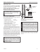
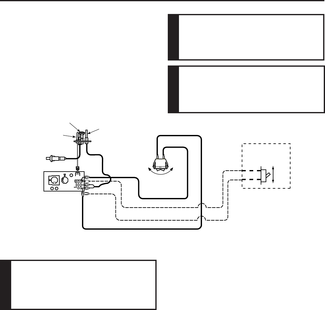
A remote wall switch and up to fteen (15) feet of 18 Ga.
wire may be used with this appliance. Attach the wall
switch in a junction box at the desired location on the
wall. Figure 30. Do not extend beyond the wall switch wire
length provided.
Figure 30 -
Wiring Diagram for Wall Switch
PILOT HI
LO
ON
OFF
FP2919
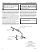
DV wiring diagram
Piezo
Ignitor
Thermocouple
Sparker
Thermopile
Pilot
Assembly
Switch
ON
OFF
Millivolt
Valve
ON
OFF
Optional 15’
Wall Switch
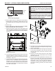
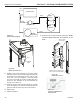
1. Before installing the blower, wire the receptacle into an
electrical circuit. This should be done before framing the
replace. Wire with minimum 60°C wire in accordance
with prevailing codes.
2. Remove the external junction box cover by removing
the screw from the right side of the outside rebox wall.
Junction box was installed at the factory.
3. The junction box cover has a factory installed “romex”
style strain relief connector. After connecting the wires,
route the wire leads through this connector. Refer to the
wiring diagram in Figure 31.
1.
2. Clean the inside of the rebox (wall and oor), where
the blower and wires will be installed. Make sure the
rebox wall and oor are clean and dry before mounting
the blower.
It is very important to arrange the blower wires
and wire assembly so that wires do not come in contact
with blower blades or rebox.
1. Remove screen rod assemblies by lifting rod and push-
ing back and down to release rod from the three hooks
located behind the face of the replace on the right, left,
and middle.
2. Remove the plate located in front of the glass at the
bottom.
3. Rotate the access doors on the right and left side of the
glass toward the glass.