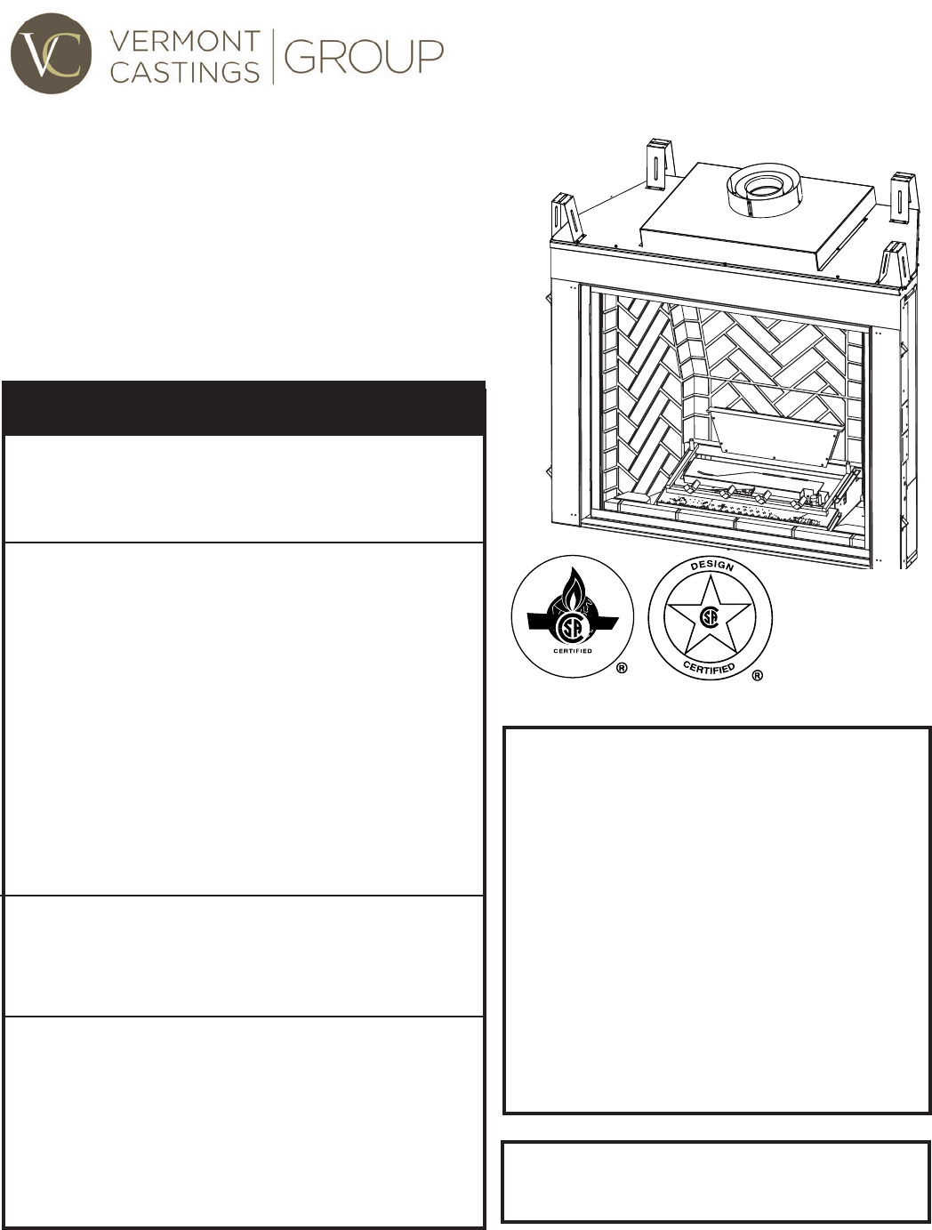
KHLDV Series Direct Vent Gas Fireplace Models: KHLDV400, KHLDV500, KHLDV600 Installation and Operating Instructions WARNING If the information in these instructions is not followed exactly, a fire or explosion may result causing property damage, personal injury or loss of life. – Do not store or use gasoline or other flammable vapors and liquids in the vicinity of this or any other appliance. – WHAT TO DO IF YOU SMELL GAS • Do not try to light any appliance.
KHLDV Series Gas Fireplace CONTENTS Thank you and congratulations on your purchase of an Vermont Castings Group Fireplace. PLEASE READ THE INSTALLATION AND OPERATION INSTRUCTIONS BEFORE USING THE APPLIANCE! IMPORTANT: Read all instructions and warnings carefully before starting installation. Failure to follow these instructions may result in a possible fire hazard and will void the warranty. Important Safety Information..................................... 3 Check Gas Pressure - Signature Command.......
IMPORTANT SAFETY INFORMATION KHLDV Series Gas Fireplace OWNER Please leave these instructions with the appliance. Please retain these instructions for future reference. WARNING INSTALLER • Read this owner’s manual carefully and completely before trying to assemble, operate, or service this fireplace. Any change to this fireplace or its controls can be dangerous.
IMPORTANT SAFETY INFORMATION and CODE APPROVAL 12. Do not use this fireplace to cook food or burn paper or other objects. 13. Never place anything on top of fireplace. 14. Do not use any solid fuels (wood, coal, paper, cardboard, etc.) in this fireplace. Use only the gas type indicated on rating plate. 15.
product features KHLDV Series Gas Fireplace • This appliance has been certified for use • • • • • • with either natural or propane gas. See appropriate data plates. This appliance is not for use with solid fuels. The appliance is approved for bedroom or bedsitting room installations. The appliance must be installed in accordance with local codes if any. If none exist use the current installation code. ANSI Z223.1/NFPA 54 in the USA, CSA B149 in Canada. This appliance is mobile home approved.
FIREPLACE and FRAMING DIMENSIONS KHLDV Series Gas Fireplace R T Min. Rough Opening Depth D E J Q H R S 1/2” or 5/8” P - Min. Rough Opening Width Min. Rough Opening Height K O I G M F Figure 2 Fireplace and Framing Dimensions L C B A Unit framing is to be rectangular front to back. Failure to do so will cause fire and damage to property. WARNING WARNING Ref.
pRE-INSTALLATION INFORMATION KHLDV Series Gas Fireplace Before You Start firebox framing Read this homeowner manual thoroughly and follow all instructions carefully. Inspect all contents for shipping damage and immediately inform your dealer if any damage is found. Do not install any unit with damaged, incomplete, or substitute parts. Check your packing list to verify that all listed parts have been received.
pRE-INSTALLATION INFORMATION KHLDV Series Gas Fireplace Fireplace Location Plan for the installation of your appliance. This includes determining where the unit is to be installed, the vent configuration to be used, framing and finishing details, and whether any optional accessories (i.e. blower, wall switch, or remote control) are desired. Consult your local building code agency to ensure compliance with local codes, including permits and inspections.
clearances KHLDV Series Gas Fireplace WARNING Clearances to combustibles 12” (305 mm) Max. Depth Follow these instructions carefully to ensure safe installation. Failure to follow instructions exactly can create a fire hazard. The appliance cannot be installed on a carpet, tile or other combustible material other than wood flooring.
SECURe FIREPLACE to floor or framing KHLDV Series Gas Fireplace The fireplace must be secured to the floor and/or to framing studs as shown in Figure 6. Use two (2) wood screws or masonry/ concrete screws to secure fireplace to the floor. Use four (4) screws to attach fireplace to framing. The side nailing flanges are 1/2" or 5/8" to accommodate different wall thickness.
WARNING venting INSTALLATION KHLDV Series Gas Fireplace Read all instructions completely and thoroughly before attempting installation. Failure to do so could result in serious injury, property damage or loss of life. Operation of improperly installed and maintained venting system could result in serious injury, property damage or loss of life. CL of pipe *3” **1” **1” INSTALLATION PRECAUTIONS 400/500 - 73” (1854 mm) Consult local building codes before beginning the installation.
VentING installation KHLDV Series Gas Fireplace • Horizontal Termination • Vertical Termination It is important to select the proper length of vent pipe for the type of termination you choose. It is also important to note the wall thickness. for horizontal termination Select the amount of vertical rise desired. All horizontal run of venting must have 1/4" rise for every 12" of run towards the termination below 7Z\x" of vertical rise from floor of fireplace.
VENTING INSTALLATION KHLDV Series Gas Fireplace General Venting Information - Termination Location INSIDE CORNER DETAIL V G H A D L V E C B V F Figure 8 Termination Locations B Fixed Closed Ope ra V B B V B V VENT TERMINATION V J A CFM145a V Fixed Closed Operable ble X AIR SUPPLY INLET X B M I V K X AREA WHERE TERMINAL IS NOT PERMITTED Canadian Installations1 US Installations2 CFM145a A = Clearance above grade, veranda, porch, 12” (30 cm)DV Termin Location 12” (30 cm
VENTING INSTALLATION KHLDV Series Gas Fireplace Termination Clearances Termination clearances for buildings with combustible and noncombustible exteriors. Alcove Applications* Inside Corner Outside Corner G= Combustible 6" (152 mm) G V F= Combustible 6" (152 mm) Noncombustible 2" (51 mm) V Noncombustible 2" (51 mm) C V O F Balcony with perpendicular side wall Balcony with no side wall D C E E = Min. 2” (51 mm) for non-vinyl sidewalls Min. 12” (305 mm) for vinyl sidewalls O = 8’ (2.4 m) Min.
ventING installation KHLDV Series Gas Fireplace Vertical Sidewall Installation NOTE: Sealant is not required to assemble fireplace venting. Do not use silicone sealant at the inner flue exhaust connections. Step 1 Locate vent opening on the wall. It may be necessary to first position the fireplace and measure to obtain hole location. Depending on whether the wall is combustible or noncombustible, cut opening to size. Figure 11 (For combustible walls first frame in opening.
VENTING INSTALLATION KHLDV Series Gas Fireplace VERTICAL/Horizontal termination configurations 36" (914 mm) Max. 36" (914 mm) Max. Since it is very important that the venting system maintain its balance between the combustion air intake and the flue gas exhaust, certain limitations as to vent configurations apply and must be strictly adhered to. The Vent Graph, showing the relationship between vertical and horizontal side wall venting, will help to determine the various dimensions allowable.
ventING installation KHLDV Series Gas Fireplace • For each 45° elbow installed in the horizontal run, the Below Grade Installations • When it is not possible to meet the required vent terminal clearances of 12" above grade level, a snorkel kit is recommended. It allows installation depth down to 7" (178 mm) below grade level. The 7" (178 mm) is measured from the center of the horizontal vent pipe as it penetrates through the wall. length of the horizontal run MUST be reduced by 18" (45 cm).
ventNG installation KHLDV Series Gas Fireplace If the foundation is recessed, use recess brackets Snorkel (not supplied) for securing Foundation lower portion Recess of the snorkel. Wall Fasten brackScrews ets to wall first, then secure to Sheet s n o r k e l w i t h Watertight Seal Metal self drilling #8 x Around Pipe Screws 1/2 sheet metal screws. It will be necessary Figure 19 to extend vent Snorkel Installation, Recessed Foundation pipes out as far FP1966 as the protruding wall face.
VENTING INSTALLATION Example: Elbow 1 Elbow 2 Elbow 3 Elbow 4 Total Angular Variation = = = = = KHLDV Series Gas Fireplace 90° 45° 45° 90° 270° For optimal flame appearance, a restrictor disk is necessary on straight vertical runs of 10' of more. • Runs may not incorporate elbows. • The disk is part number 56D3027 and is included in • 1 1 2 •2 3 3 installation manual packet.
VENTING INSTALLATION KHLDV Series Gas Fireplace /" 10 1 2 101 4. Connect a section of pipe and extend up through the hole. NOTE: If an offset is needed to avoid obstructions, you must support the vent pipe every three (3) feet. Use wall straps for this purpose. Refer to Page 18, Figure 21. Whenever possible, use 45° elbows instead of 90° elbows. The 45° elbow offers less restriction to the flow of the flue gases and intake air. 5. Place the flashing over the pipe section(s) extending through the roof.
fireplace installation KHLDV Series Gas Fireplace check gas type Use proper gas type for the fireplace you are installing. If you have conflicting gas type, do not install fireplace. See dealer where you purchased the fireplace for proper fireplace for your gas type or conversion kit. External Regulator 100 gallon (min) Propane/LP Supply Tank WARNING Installing gas piping to fireplace / burner system location A qualified installer or service person must connect appliance to gas supply.
fireplace installation CAUTION Only persons licensed to work with gas piping may make the necessary gas connections to this appliance. NOTE: The gas line connection may be made using 1/2" rigid tubing or an approved flex connector. Since some municipalities have additional local codes it is always best to consult your local authorities and the current edition of the National Fuel Gas Code ANSI.Z223.1, NFPA54. In Canada CSA-B149 (1 or 2) Installation Code.
MILLIVOLT - CHECK GAS PRESSURE and Electrical installation KHLDV Series Gas Fireplace WARNING 1. Check gas type. The gas supply must be the same as stated on the appliance’s rating decal. If the gas supply is different from the fireplace, STOP! Do not install the appliance. Contact your dealer immediately. 2. To ease installation, a 24" (610 mm) flex line with manual shut-off valve has been provided with on this appliance. Install and attach 3/8" gas line onto shut-off valve. 3.
A remote wall switch and up to fifteen (15) feet of 18 Ga. wire may be used with this appliance. Attach the wall switch in a junction box at the desired location on the wall. Figure 30. Do not extend beyond the wall switch wire length provided. NOTE: Extended lengths of wire may cause the fireplace not to function properly. Longer length of wire is permitted if the wire is made out of larger gauge (diameter) wire. Always check with local code.
millivolt - OPTIONAL FAN/BLOWER SYSTEM Junction Box Figure 31 Junction Box Wiring Diagram WARNING Factory Supplied Not Supplied Failure to replace the access cover with the one provided with the blower kit, and then running the blower, will cause excessive temperatures and could cause a fire, property damage and/or loss of life.
millivolt - OPTIONAL FAN/BLOWER SYSTEM KHLDV Series Gas Fireplace Blue Junction Box Blue Black Hi-Temp Black Hi-Temp T-Stat Sensor Black Black Right Blower Left Blower White Black Blower Rheostat Figure 34 Blower Wiring Diagram 18. Replace the front plate below the glass frame. NOTE: The front plate hides the wire harness in the front.
millivolt - OPERATING INSTRUCTIONS KHLDV Series Gas Fireplace WARNING for your safety read before lighting If you do not follow these instruction exactly, a fire or explosion may result causing property damage, personal injury or loss of life. A. This appliance is equipped with a pilot which must be lit with built-in piezo ignitor while following these instructions exactly. B. BEFORE OPERATING smell all around the appliance area for gas.
millivolt - OPERATING INSTRUCTIONs KHLDV Series Gas Fireplace approved leak testing method You may check for gas leaks with the following methods only: • Soap and water solution WARNING Lighting pilot for the first time If using a soap and water solution to test for leaks, DO NOT spray solution onto control body. • An approved leak testing spray DANGER • Electronic sniffer NOTE: Remove any excessive pipe compound from the connections. Excessive pipe compound can set off electronic sniffers.
millivolt - OPERATING INSTRUCTIONS KHLDV Series Gas Fireplace Lighting burner Lighting the burner Depress and turn the knob counterclockwise to the “ON” position. It will take less than four (4) seconds for the burner to ignite. OFF RS The “ON/OFF/RS” switch for the main burner can be found behind door of the fireplace. This switch allows you to turn on and to turn off the main burner without using the gas valve knob. Make sure the button is in the “ON” position to light the main burner.
SIGNATURE COMMAND - CHECK GAS PRESSURE and ELECTRICAL INSTALLATION KHLDV Series Gas Fireplace 1. Check gas type. The gas supply must be the same as stated on the appliance’s rating decal. If the gas supply is different from the fireplace, STOP! Do not install the appliance. Contact your dealer immediately. 2. To ease installation, a 24" (610 mm) flex line with manual shut-off valve has been provided with on this appliance. Install and attach 1/2" gas line onto shut-off valve. 3.
ELECTRICAL INSTALLATION KHLDV Series Gas Fireplace JUNCTION BOX WIRING 1. This should be done before framing the fireplace. Wire the receptacle into an electrical circuit. Wire with minimum 60° C wire in accordance with prevailing codes. 2. Remove the external junction box cover by removing the screw from the side of the outside firebox wall. Junction box was installed at the factory. 120V AC 3. The junction box cover has a factory installed “romex” style 60Hz strain relief connector.
ELECTRICAL INSTALLATION KHLDV Series Gas Fireplace Light 300 Watt Max A/C Module To Outlet Pilot Optional Blower 300 Watt Max Rear Burner Solenoid 300 Watt Max RF Receiver ON/OFF Button A/C Module Control Board Black / Thermopile Red / Thermopile Sensor Conversion NG/LP Ignitor / Sparker Plug-in Connector Control Board to Command Center NOTE: Wall switch wires must be connected together if a wall switch is not being used.
The black and white wires on the AC box wiring harness are marked ‘Blower’, ‘Light’ and ‘Aux’. It is important to use the wires marked ‘Blower’ or the control will not work correctly. WARNING WARNING Electrical Grounding Instructions: This appliance is equipped with a three-prong (grounding) plug for your protection against shock hazard and should be plugged directly into a properly grounded three-prong receptacle.
signature command - OPERATING INSTRUCTIONS KHLDV Series Gas Fireplace WARNING for your safety read before lighting If you do not follow these instructions exactly, a fire or explosion may result causing property damage, personal injury or loss of life. A. This appliance is equipped with an ignition device which automatically lights the pilot. Refer to the instructions. B. BEFORE OPERATING smell all around the appliance area for gas.
signature command - OPERATING INSTRUCTIONS KHLDV Series Gas Fireplace OPERATing INSTRUCTIONS 1. STOP! Read the safety information above. 2. This appliance is equipped with an ignition device which automatically lights the burner. Do not try to light the burner by hand. 3. With five (5) minutes to clear out any gas. Then smell for gas, including near the floor. If you smell gas, STOP! Follow "B" in the safety information on Page 34. If you do not smell gas, go to next step. 4.
KHLDV Series Gas Fireplace SIGNATURE COMMAND SYSTEM OPERATION INSTRUCTIONS FEATURES RF Receiver ON/OFF Command Center To Thermopile To Sensor To Sparker • Easy Access Function Operation and System Configuration NG/LP Conversion • Operation Confirmation/Fault Diagnostic Indications (LED/Buzzer) • ON/OFF/HI/Med/Low Operation • Optional Wall Mounting Control Board • Electronic Ignition • Pilot Lockout safety feature • Electric Power Regeneration from Thermopile to save • • • • • • • To Command Cente
SIGNATURE COMMAND SYSTEM OPERATION INSTRUCTIONS SYSTEM CONFIGURATION/SETUP All System configuration/setup is done on the Command Center. NOTE: When using On/Off wall switch, the switch must be in the ON position to perform all configuration set ups at the command center. COLD CLIMATE OPTION Choose the Mode That Best Suits Your Needs The Signature Command System is designed to operate in either Standing Pilot or Intermittent Pilot mode.
KHLDV Series Gas Fireplace SIGNATURE COMMAND SYSTEM OPERATION INSTRUCTIONS FUNCTIONS/OPERATION (with Command Center) Turning on the fireplace 1. Turn on the master switch and wait for a beep. 2. Press the ON button on the Command Center or turn on wall switch. Pilot will light and burner will come on High setting or last memory setting (See Turning Off Fireplace below). For memory feature. Pilot Safety Lockout Function 1.
WARNING Information Bar The information bar shows the room temperature, the “sending signal” radio icon, the low battery indication icon, the child-proof icon, and the flame icon. This area doesn’t have touch buttons. • The room temperature will always be shown after • • • • power-up. It displays the room temperature from 40 °F to 99 °F. “Lo” and “HI” will be displayed when the room temperature is lower than 40°F or higher than 99°F, respectively.
KHLDV Series Gas Fireplace TOUCH SCREEN REMOTE CONTROL OPERATION Setting Privacy Code on Transmitter: Figure 45 ON The remote transmitter privacy code is preset in factory. In the event of activation or interference from other nearby transmissions, change the code using the following procedures (learn function must be performed after changing the code): OFF 1.
TOUCH SCREEN REMOTE CONTROL OPERATION THERMO, LIGHT, FAN, AUX) are pressed and flashing. 1. Press the ON/up button to turn on the fireplace. The flame icon on the LCD displays High. 2. Press the OFF/down button to decrease the flame height and turn off the fireplace. When the OFF/down button is pressed for three times, the flame icon changes form High to Medium, to Low, then to Off. 3.
KHLDV Series Gas Fireplace TOUCH SCREEN REMOTE CONTROL OPERATION Temperature. The transmitter will automatically adjust the flame height according to the difference between the Set temperature and the Room temperature. There is no manual flame height adjustment. The fan speed will also automatically adjust if turned on. NOTE: When entering the Smart Mode® thermostat function there will be a 10 second delay for the flame and blower adjustment.
TOUCH SCREEN REMOTE CONTROL OPERATION 3. Press the light button again to confirm the setting. The new setting will be transmitted to the receiver. 4. After the signal is sent, the On/up and Off/down buttons become flame height controller again. 5.
TOUCH SCREEN REMOTE CONTROL OPERATION KHLDV Series Gas Fireplace n Using the Mounting Base The transmitter comes with a mounting base which allows you to hang the transmitter on the wall. 1. Secure the mounting base on the wall with supplied screws. For best viewing angle, make it the same height as your eyes. 2. Hang the transmitter on the hook of the mounting base, then push down so the transmitter is flush to the mounting base. Figure 56 FP2674 TROUBLESHOOTING mounting base Symptom Causes Action 1.
glass removal KHLDV Series Gas Fireplace 1. Remove the plate located in front of the glass at the bottom. 2. Remove rod provided for screen assembly located beneath the cover plate. 3. Rotate the access doors on the right and left side of the glass toward the glass. 4. Remove glass frame by releasing the three latches located at the top of the firebox. Tilt glass away from the unit, lift glass frame up and away from the unit. Figure 57 CAUTION Glass Frame Removal Each clamp has a quick spring force.
final installation KHLDV Series Gas Fireplace BRICK, light bulb, and lens placement - 400/500 Series BRICK, light bulb, and lens placement - 600 Series 1. Remove the trapezoidal light shroud located at the back of the firebox by unfastening the three screws. 2. Disassemble the trapezoidal light shroud by unfastening the four screws which secure the front to the back. Set lens with the orange painted surface toward the bottom. Center the lens right to left.
final installation KHLDV Series Gas Fireplace ROCK WOOL PLACEMENT - 600 SERIES rock wool placement 400/500 Series 1. Place rock wool on the front burner to provide glowing embers. For best results, pull the rock wool apart into dime size pieces and place on top of burner. Also place the same size ember over the carry over parts on the rear burner. Do not place embers over open slots on the rear burner. 2. Distribute one layer of rock wool to cover the burner. Figure 61 3. Place the logs on the burner.
log placement KHLDV Series Gas Fireplace lOG placement - 400/500 Series LG593 Burner Grate Assembly Step 1 LG594 1. Place the rear log over the grate toward the back by positioning the holes over the large pins located LG593 at the right grate and left. When the log is in place, the back surface of the log will come in contact with KHLDV LG594 the light trapezoid deflector. KHLDV rear log 2.
log placement KHLDV Series Gas Fireplace 4. Place the middle log over the two burners by setting the flat surface over the burner and matching the indentation located underneath the branch over the protrusion located at V-branch on the left front log placed in step #3. Rotate the right end of the log clockwise until it comes in contact with the reverse bend on the bracket located between the front and rear burner. Step 4 LG597 LG597 5.
log placement KHLDV Series Gas Fireplace ROCK WOOL PLACEMENT 600 SERIES Place rock wool evenly in dime-sized pieces over front burner both in front and behind grate. For the rear burner, place the rock wool only on the carryover areas between the flames. To better enable the gas to permeate the rock wool, apply the rock wool in light, fluffy pieces. LG918 LOG PLACEMENT 600 SERIES 1. Hold log #1 with the key to the top LG918 600 embers and to the right side of center and the notches on the bottom.
log placement KHLDV Series Gas Fireplace 3. Hold log #3 with the hole for the pin toward the back left corner. Position the log on the pin provided on the back left corner of the grate. Place the right end of the log in the notch provided on the back left corner of the grate. Place the right end of the log in the notch provided on the top of log #2. Insure the log is seated securely. 4. Hold log #4 with the notch on the bottom and toward theLG921 back of the unit.
log placement KHLDV Series Gas Fireplace Log #6 LG923 Log #7 6. Hold log #6 in your right hand with the charred detail to the right and the notches on the bottom. Position the log on top of the keys provided on the top of log #5 in the front and log #3 in the back. NOTE: Log #6 will help to hold log #5 in place. 7. Hold log #7 with the pointed end to the left and the notch on the bottom. Place the pointed end of the log on the hearth brick in front of the burner and under the third time from the right.
cleaning and maintenance KHLDV Series Gas Fireplace WARNING Sensor Turn off gas before servicing fireplace. It is recommended that a qualified service technician perform these check-ups at the beginning of each heating season Burner, Pilot and Control Compartment Keep the control compartment, logs, and burner areas surrounding the logs clean by vacuuming or brushing at least twice a year. Make sure the burner porting, pilot air opening and burner air opening are free of obstructions at all times.
cleaning and maintenance KHLDV Series Gas Fireplace Venting SysteM The fireplace and venting system should be inspected before initial use and at least annually by a qualified field service person. Inspect the external vent cap on a regular basis to make sure that no debris is interfering with the airflow. Inspect entire venting system to ensure proper function. Glass Door Thoroughly clean the inside of the glass door after using the fireplace for ten hours. Periodically clean the glass door as necessary.
troubleshooting KHLDV Series Gas Fireplace Standing Pilot Ignition SYMPTOM POSSIBLE CAUSE ACTION 1. Spark ignitor will A. Wire disconnected. not light pilot after repeated triggering of B. Defective ignitor. piezo. C. No gas or low gas pressure. D. No Propane/LPG in tank 2. Pilot will not stay lit A. Defective thermocouple after carefully following lighting instructions. B. Defective valve 3. Pilot burning, valve A.
troubleshooting KHLDV Series Gas Fireplace Standing Pilot Ignition SYMPTOM POSSIBLE CAUSE ACTION 4. Frequent pilot outage problem. A. Pilot flame may be too high or too low, causing pilot safety to drop out A. Clean and adjust the pilot flame for maximum flame impingement on thermocouple. 5. The pilot and main burner extinguish while in operation A. Inner vent pipe leaking exhaust gases back into system B. Horizontal vent improperly pitched C. Improper vent cap installation A.
troubleshooting KHLDV Series Gas Fireplace SIGNATURE COMMAND SYSTEM OPERATION Install batteries and/or plug in the AC board FAULT No beep in about 8 seconds A Using battery? Make sure Command Center and the control board are connected by a 2 feet or 15 feet cable After the beep Flip the master switch (rocker switch) to the ON position Press the ON button on the Command Center No beep or no sound from the valve indicating pilot solenoid open B No sparking on the pilot C Sparking doesn’t conti
REPLACEMENT PARTS KHLDV Series Gas Fireplace firebox components and accessories 2 3 1 6 11 5 9 12a,b 10 10 7a,b 8 Item Description Qty. KHLDV400 1. Bulb (100 Watt) 2 73D0020 730024 2. Bulb Socket 2 73D4521K KHLDV firebox parts 3. Glass Frame Assembly 1 73D1015K 4. Junction Box Assembly (not shown) 1 26D2128K 5. Light Lens (400/500 Series) 1 73D0022 5. Light Lens (600 Series) 2 -6. Panel, Access, Door 2 73D0029K 7a. Firebrick Set - Tavern Brown 1 FBKHLDV400TB 7b.
REPLACEMENT PARTS KHLDV Series Gas Fireplace Standing Pilot — Millivolt control 2I 2C 1 2T 3 2 6 4 5 7 10 8 11,12,13,14 730024 khldv mv valve parts 73D0024 59
REPLACEMENT PARTS KHLDV Series Gas Fireplace Standing Pilot – Millivolt Control Item 1. 2. 2C. 2I. 2T. 3. 3. 3. 3. 4. 5. 6. 7. 7. 8. 8. 9. 10. 10. 11. 12. 13. 14. 15. 15. Description Qty.
REPLACEMENT PARTS KHLDV Series Gas Fireplace SIGNATURE COMMAND SYSTEM 400 Series 13 Venturi Gasket 8a 9 7a 6 15 8b 5a 5d 2 5c Shield, Pilot 1 7b 4 3 17, 18 5b 14 5e Flex Hose 20H0022 Shield, Pilot 6 8a 3 8b Flex Hose 20H0022 7a Venturi Gasket 2 500 Series 14 5a 5d 13 17,18 1 3 15 9 7b 5b 5e 600 Series 8a 5c 1 6 8b 4 5a 2 7a 9 5b Flex Hose 20H0022 7b 3 5g 16 15 5f 14 73D0024 61
REPLACEMENT PARTS KHLDV Series Gas Fireplace SIGNATURE COMMAND SYSTEM Item Desc. Qty. 1. Gas Valve Assembly 1 2. Pilot Assembly 1 3. Control Box, auxiliary shut-off 1 4. Command Center SCS 1 5a. Tube, Rear, Venturi 1 5b. Tube, Front, Venturi 1 5c. Rear Tube, Tee to Solenoid 1 5d. Rear Tube, Solenoid to Venturi 1 5e. Tube, Front, Through-wall 1 5f. Rear Tube, Solenoid to Union 1 5g. Front Tube, Tee to Union 1 6. Flexhose w/Shutoff Valve 1 7a. Rear Injector 1 7b. Front Injector 1 8a.
REPLACEMENT PARTS KHLDV Series Gas Fireplace logs KHLDV400 & KHLDV500 LOGS 6 3 2 4 KHLDV600 LOGS 7 5 Item 1. 2. 3. 4. 5. 6. 7. Description Qty.
REPLACEMENT PARTS KHLDV Series Gas Fireplace VENTing components 1 2 3 4 HO T 10 5 6 9 7 8 730024 KHLDV vent parts 64 73D0024
REPLACEMENT PARTS KHLDV Series Gas Fireplace Venting Components for 5"x 8" Current Old Duravent Duravent or Vermont or Vermont Qty./ Castings Group Castings Group Selkirk Metal-Fab Item Box Description Part no. Part no. Part no. Part no.
KHLDV Series Gas Fireplace Requirements for the Commonwealth of Massachusetts This product must be installed by a licensed plumber or gas fitter when installed within the Commonwealth of Massachusetts. Note Regarding Vented Products Flex line installation must not exceed 36 inches and must have a T shutoff valve. Any residence with a direct vent product must have a CO detector installed in the residence.
KHLDV Series Gas Fireplace Limited lifetime warranty policy Lifetime Warranty The following components are warranted for life to the original owner, subject to proof of purchase: Firebox, Combustion Chamber, Heat Exchanger, Grate and Stainless Steel Burners. Five Year Warranty The following components are warranted five (5) years to the original owner, subject of proof of purchase: Ceramic Fiber Logs.
Based on CSA P.4.1-09 Efficiency Ratings Model EnerGuide Ratings Fireplace Efficiency (%) KHLDV400NV 69.6 KHLDV400PV 78.2 KHLDV400NTSC Recherchez dans la73.2 brochure KHLDV400PTSC 82.2 les caractéristique de rendement KHLDV500NV 75.2au gaz énergétique de foyer KHLDV500PV 69.8 Énerguide KHLDV500NTSC 78.5 Based CSA P.4.1-09 Selonon CSA P.4.1-09 KHLDV500PTSC 71.8 KHLDV600NTSC 81.0 KHLDV600PTSC 80.0 Vermont Castings Group 149 Cleveland Drive • Paris, Kentucky 40361 www.vermontcastingsgroup.