Irving Oil INSTALLER/CONSUMER SAFETY INFORMATION PLEASE READ THIS MANUAL BEFORE INSTALLING AND USING APPLIANCE WARNING! IF THE INFORMATION IN THIS MANUAL IS NOT FOLLOWED EXACTLY, A FIRE OR EXPLOSION MAY RESULT CAUSING PROPERTY DAMAGE, PERSONAL INJURY OR LOSS OF LIFE. Freestanding Direct Vent Fireplaces IRFSDV24 IRFSDV34 FOR YOUR SAFETY Installation and service must be performed by a qualified installer, service agency or the gas supplier.
Irving Oil TABLE OF CONTENTS PLEASE READ THE INSTALLATION & OPERATING INSTRUCTIONS BEFORE USING APPLIANCE. Thank you and congratulations on your purchase of a Irving Oil fireplace. IMPORTANT: Read all instructions and warnings carefully before starting installation. Failure to follow these instructions may result in a possible fire hazard and will void the warranty. Installation Instructions ................................................................................................................
Irving Oil INSTALLATION & OPERATING INSTRUCTIONS This gas fireplace should be installed by a qualified installer in accordance with local building codes and with current CSA-B149 (.1 or .2) Installation codes for Gas Burning Appliances and Equipment. For USA Installations follow local codes and/or the current National Fuel Gas Code. ANSI Z223.1. If the unit is being installed in a mobile home the installation should comply with the current CAN/USA Z240.4 Code.
Irving Oil FIREPLACE DIMENSIONS IRFSDV24 4 IRFSDV34 A 23 in (584 mm) A 26-14 in (667 mm) B 28-3/4 in (730 mm) B 31-1/2 in (800 mm) C 16-5/8 in (422 mm) C 19-3/8 in (492 mm) D 27-3/8 in (695 mm) D 30 in (762 mm) E 9-1/2 in (241 mm) E 10 in (254 mm) F 13-7/8 in (352 mm) F 15-1/2 in (394 mm) G 4 in (102 mm) G 4-1/2 in (114 mm) H 23 in (584 mm) H 26-1/4” (667 mm) I 11-1/2 in (292 mm) I 13-1/8 “ (334 mm) J 16-5/8 in (422 mm) J 19-1/2” (495 mm) K 6” (152 mm) K 6-3/8
Irving Oil GAS SPECIFICATIONS Model PREPARATION Max. Max. Input Input Fuel Gas Control BTU/h BTU/h IRFSDV24RN Nat Millivolt Hi/Lo 20,000 14,000 IRFSDV24RP Prop Millivolt Hi/Lo 20,000 15,000 IRFSDV34RFN Nat Radio Frequency 30,000 21,000 IRFSDV34RFP Prop Radio Frequency 30,000 22,500 This appliance may be installed in an aftermarket permanently located, manufactured (mobile) home, where not prohibited by local codes.
Irving Oil When using copper or flex connector use only approved fittings. Always provide a union when using black iron pipe so that gas line can be easily disconnected for burner or fan servicing (see Fig. 2) See gas specification for pressure details and ratings. The fireplace valve must not be subjected to any test pressures exceeding 1/2 psi. Isolate or disconnect this or any other gas appliance control from the gas line when pressure testing.
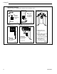
Irving Oil GENERAL VENTING INFORMATION–TERMINATION LOCATION INSIDE CORNER DETAIL G V H A D V N N E V B C V L B Fixed Closed Ope F B V Operable rab V le V Fixed Closed G V B B B V J M X I A V VENT TERMINATION X AIR SUPPLY INLET G V K X V A AREA WHERE TERMINAL IS NOT PERMITTED CFM145a Canadian Installations 1 US Installations 2 A = Clearance above grade, veranda, porch, deck, or balcony B = Clearance to window/door that may be opened 12 inches (30cm) 12 inches (30
Irving Oil Termination Clearances Termination clearances for buildings with combustible and noncombustible exteriors. Inside Corner Recessed Location Outside Corner A= Combustible 6"(152mm) Noncombustible 2"(50mm) A V B= Combustible 6"(152mm) Noncombustible 2"(50mm) V D C C E V B Fig. 6 Fig. 7 Balcony with perpendicular side wall Balcony with no side wall C = Maximum depth of 48" (1219mm) for recessed location. H G V V G= Combustible 24"(610mm) Non-Combustible 18"(457mm) Fig.
Irving Oil GENERAL INFORMATION ON ASSEMBLING THE VENT PIPES IN DIRECT VENT APPLICATIONS NOTE: Only venting components manufactured by The Vermont Castings Majestic Products Company may be used. TWIST LOCK PIPES CRIMPED END PIPES Before joining elbows and pipes apply a bead of high temperature sealant to the crimped end of the elbow or pipe. Join the pipes using a 2” (50mm) overlap and secure the joints with three (3) sheet metal screws (Fig. 11). Wipe off excess sealant.
Irving Oil VERTICAL SIDEWALL INSTALLATIONS Since it is very important that the venting system maintain its balance between the combustion air intake and the flue gas exhaust, certain limitations as to vent configurations apply and must be strictly adhered to.
Irving Oil TO USE THE VENT GRAPH 1. Determine the height of the center of the horizontal vent pipe exiting through the outer wall. Using this dimension on the Sidewall Vent Graph below, locate the point it intersects with the slanted graph line. 2. From the point of this intersection, draw a vertical line to the bottom of the graph. 3. Select the indicated dimension, and position the fireplace in accordance with same. Example A: If the vertical dimension from the floor of the fireplace is 11’ (3.
Irving Oil VENT PIPE ASSEMBLY STEP 1 Locate vent opening on the wall. It may be necessary to first position the fireplace and measure to obtain hole location. Depending on whether the wall is combustible or noncombustible, cut opening to size (Fig. 17). (For combustible walls first frame in opening. Fig. 17) Vent Opening Combustible Wall STEP 3 Place fireplace into position (Fig. 19). Measure the vertical height (X) required from the base of the flue collars to the center of the wall opening.
Irving Oil STEP 5 Measure the horizontal length requirement including a 2” (50 mm) overlap, i.e. from the elbow to the outside wall face plus 2” (or the distance required if installing a second 90° elbow (Fig. 21). ,, , ,, , ,, ,, ,, X Fig. 21 Always install horizontal venting on a level plane. STEP 6 Note: If using the charcoal wall plate, Part #52202-CG, and collar, Part #52203-CG, put them in place before putting the pipe sections through the wall.
Irving Oil If installing a snorkel a minimum 24” vertical rise is necessary. The maximum horizontal run with the 24” vertical pipe is 36” (915 mm). This measurement is taken from the collar of the fireplace to the face of the exterior wall. See the Vent Chart on page 11 for extended horizontal run if the vertical rise exceeds 24”. FOUNDATION RECESS WATERTIGHT SEAL AROUND PIPE 1. Establish vent hole through the wall (Fig. 17). 2. Remove soil to a depth of approximately 16" (406mm) below base of snorkel.
Irving Oil • installations. From 0 to a maximum of 8’ of vent pipe can be used between elbows (Fig. 25). 7DVCS must be used to support offsets (Fig. 26). This application will require that you first determine the roof pitch and use the appropriate starter kit. (See Venting Components List) MAX. 8 FEET 2.44m 45° 40'(12m) MAX. 8 FEET 2.44m TYPICAL 7DVCS APPLICATION 45° TO INSTALL VERTICAL VENTING 1. Locate your fireplace. 2. Plumb to center of the (4”) flue collar from ceiling above and mark position.
Irving Oil CRIMPED END VENTING COMPONENTS Starter Kit-Model 7FSDVSK-Sidewall Venting Starter Kit-Model 7TDVSKV-Vertical Venting for 7DVSKV-A order 1/12 to 6/12 roof pitch for 7DVSKV-B order 7/12 to 12/12 roof pitch for 7DVSKV-F order flat roof Starter Kit-Model 7FSDVSKS-Snorkel Kit for Below Grade Installation 45˚ elbow kit 7FSDVT45G for Vertical Installation Offsets 90˚ Transition elbow kit 7DVRT90 for Vertical Sidewall Applications or through-the-roof.
Irving Oil TWIST LOCK VENTING COMPONENTS Starter Kit - Model 7TFSMSK Starter Kit-Model 7TFSDVSK-Sidewall Venting Starter Kit-Model 7TDVSKV - Vertical Venting for 7TDVSKV-A order 1/12 to 6/12 roof pitch for 7TDVSKV-B order 7/12 to 12/12 roof pitch for 7TDVSK-F order flat roof Starter Kit-Model 7TFSDVSKS-Snorkel Kit for Below Grade Installation 45˚ elbow kit 7TFSDV45 for Vertical Installation Offsets 90˚ Transition elbow kit 7TFSDV90 for Vertical Sidewall Applications or through-the-roof.
Irving Oil OPERATING INSTRUCTIONS GENERAL GLASS INFORMATION Only glass approved by the Vermont Castings, Majestic Products Company may be used for replacement. • • The use of substitute glass will void all product warranties. Care must be taken to avoid breakage of the glass. Under no circumstances should this fireplace be operated without the front glass or with a broken glass. Replacement of the glass (with gasket) as supplied by the manufacturer should be done by a licensed qualified service person.
Irving Oil INSTALLATION OF LOGS & BURNER LAVA ROCK MATERIAL (Cont.) Model: IRFSDV24 Refer Figure 33. 1. Remove window frame assembly (See Window Frame Assembly section). 2. Remove logs from packaging. As with all plastic - these are not toys and should be kept away from children and infants. 3. Place rear left log (KR15) with one end onto the left rear bracket while the rest of the log sets on the center of the rear log support. 4. Fit the rear right log (KR16) onto the right side of the rear log support.
Irving Oil FLAME & TEMPERATURE ADJUSTMENT RN/RP Models For units equipped with ‘HI/LO’ valves the flame adjustment is accomplished by rotating the ‘HI/LO’ knob located near the center of the gas control valve (See Fig. below). IRFSDV24 Turn counterclockwise to decrease flame height Fig. 35 Turn clockwise to increase flame height Honeywell Valve FLAME CHARACTERISTICS It is important to periodically perform a visual check of the pilot and burner flames.
Irving Oil REMOTE CONTROLS OPTIONAL FRAME WINDOW TRIM KITS These remote controls are available as an option only on fireplaces fitted with RN/RP gas control valves. IRFSDV24 model only. MRC1 MRC2 MRC3 IMT On/Off Button Remote Control Temperature Control Remote Temperature Control w/digital display & 24 hour programmable clock Wall Mounted Thermostat OPTIONAL GOLD TRIM KIT A decorative gold plated window trim kit Model #VT1G00 RFSDV24TKG is available for the IRSFD24 Freestanding Fireplace.
Irving Oil LIGHTING AND OPERATING INSTRUCTIONS FOR YOUR SAFETY READ BEFORE LIGHTING WARNING: If you do not follow these instructions exactly, a fire or explosion may result causing property damage, personal injury or loss of life. A. This fireplace has a pilot which must be lit manually. When lighting the pilot follow these instructions exactly. B. BEFORE LIGHTING smell all around the fireplace area for gas.
Irving Oil OPERATING INSTRUCTIONS FOR RFN/RFP COMFORT CONTROL VALVE The Comfort Control Valve allows remote control of temperature, fan and flame appearance. NOTE: The antenna should hang in free air away from grounded metal. OPERATION 7. If the manual switch is in the LOCAL position, the valve will be at the highest fixed pressure setting and the fan will be at the highest fixed speed. The transmitter will control the fan only. SHUT OFF PROCEDURE 1.
Irving Oil Delay Timer Mode Pilot Assembly The shut off delay timer has a maximum of 2 hours and a minimum of zero minutes. To change the timer level, press the time key followed by an arrow key. Pushing the key once will change the timer by 10 minutes. Fan Auto Mode In the AUTO mode, the room temperature, set temperature, flame and fan levels will be shown. AUTO will appear next to both the flame and fan icons.
Irving Oil TROUBLE SHOOTING THE GAS CONTROL SYSTEM Comfort Valve system control sequence of operation with transmitter Local Path Set manual switch to local or remote Five minute wait period Light pilot burner Did the LED stop blinking? If manual switch is set to LOCAL, did main buen light and fan turn on? Move switch from manual to remote. Press any key on transmitter. Move switch back to manual. Yes No Review LED failure analysis Turn pilotstat knob to PILOT to turn off main burner.
Irving Oil REPLACEMENT PARTS LIST Code # 1 1a 1b 1c 1d 1e 1f 1g 1h 2* 3 4* 5a* 5b* 5c* 5d* 6a* 6b* 7a* 7b* 8a 8b 9a 9b 9c 9d 10 11a 11b 12* 13a 13b 14 15 16* 17 18a 18b 18c 18d 19* 26 Part Description Log Set Complete Log ember bed Log - Front left Log - Front right Log - Rear Log - Top left Log - Top right Log - Rear left Log - Rear right Lava Rock Burner Housing Assembly (with tiles) Ceramic Tile (singular) Orifice, Main Burner - Nat. Orifice, Main Burner - Prop.
Irving Oil REPLACEMENT PARTS LIST Code# IRFSDV24 IRFSDV34 20 Fan Assembly with bracket Part Description 54103 54103 21 Remote ON/OFF Switch 53606 53606 22* Wiring Harness - Remote Switch 57265 57265 23* Remote ON/OFF Switch Kit (includes bracket) 53859 53859 24 Window Frame Assembly (complete with glass) 10003973 10003966 25* Window Glass with Gasket Assembly Kit 10003974 10003965 26* Window Glass Gasket Kit 10001983 10001983 27 Front Louvre Assembly 10003537 10001370 28
Irving Oil REPLACEMENT PARTS 13b 20 3 10 9c/d 34 39 13b 9a/b 40 32 14 37 11a 17 13a 27 21 11b 8a/b 30 24 38 11a 29 28 14 18c/d 15 14 OFF PILOT ADJ OFF ON OT ON P I O H L PI L I LO T 18a/b 31 1e 1g 1f 1h 1d 1c 1b 1b 1c IRFSDV24 Log Set 28 1a IRFSDV34 Log Set 10004000