
Operating instructions


24
Chateau™ Decorative Gas Appliance
20007172
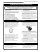
It is important to periodically perform a visual check of
the pilot and burner flames. Compare them to the
illustratrations below. (Figs. 46, 47)
If the flame patterns appear abnormal contact a
qualified service provider for service and adjustment.
Flame Characteristics
L
O
H
I
Turn
counterclockwise
to increase
flame height
Turn clockwise
to decrease
flame height
SIT 820 Valve
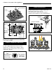
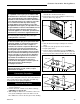
Fig. 45 Flame adjustment knob for SIT valve.
Flame & Temperature Adjustment
RN/RP & EN/EP Models
For units equipped with ‘HI/LO’ valves the flame
adjustment is accomplished by rotating the ‘HI/LO’
adjustment knob located near the center of the gas
control valve. (Fig. 45)
3/8" - 1/2"
SIT Top Convertible
SIT EN/EP
FP1229a
Fig. 46 Correct pilot flame appearance.
Fig. 47 DVT38S2 burner flame pattern.
LG330
LG328
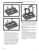
Fig. 43 Place logs F5, F6 and F10.
Log Top Center (F10)
Log Top Middle (F5)
Log Top
Left (F6)
13⁵⁄₈"
(346mm)
1¹⁄₂"
(38mm)
16¹⁄₄"
(413mm)
Refractory
Line
Firebox
Fettle Line
Top View
LG338
Fig. 44 Log top center (F10) must be placed according to
these dimensions. NOTE: This view is shown without lava
rock or embers for clarity.
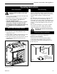
Valve Box
Assembly
Side