
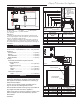
Operating instructions

6
Chateau™ Decorative Gas Appliance
20009543
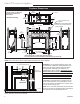
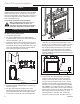
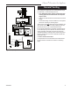
A hearth is not mandatory but is recommended for
aesthetic purposes. We recommend a noncombustible
hearth which projects out 12” (305 mm) or more from
the front of the fireplace. The hearth cannot exceed 1¹⁄₂”
(38 mm) in height from bottom of fireplace for ease of
door accessibility. (Fig. 4)
Cold climate installation recommendation:
When installing this unit against a non-
insulated exterior wall or chase, it is
mandatory the outer walls be insulated to
conform to applicable insulation codes.
Hearth
Framing and Finishing
NOTE: The valve box assembly must be installed in
the same room as the fireplace.
1. Choose the unit location.
2. The unit is shipped with four (4) nailing flanges
mounted near the front corners on the side with the
valve box assembly . (Fig. 4)
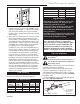
3. Frame the fireplace with a header across the top of
the standoff. (Fig. 5) It is very important to allow for
the finished wall face along with marble, tiles or any
other noncombustible face finish material desired
when setting the depth of the framing.
FP1357b
DVT38s2nailing flanges
3/17/04 djt
6"
(152 mm) Min.
1"
(25 mm) Min.
1"
(38mm)
Max. Hearth Height
FP1357a
Fig. 4 Nailing flanges.
Bend
Line
FP1467a
DVT38s2
framing
6/05 djt
1"
(25 mm)
6"
(152 mm)
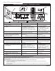
Fig. 5 Fireplace framing.
FP1467a
FP1361
Fig. 6 Valve box assembly location.
4. Attach the fireplace nailing flanges to the frame as
shown in Figure 4.
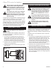
5.
The gas components are located in the control
panel assembly attached to the right side of the unit.
Choose the desired location on the wall or mantel
for the valve box assembly. The conduit length is 5’
(1524 mm). (Fig. 6) The framing dimensions for the
box are 12¹⁄₄”L x 9¹⁄₄”W x 5⁵⁄₈”D (311 x 235 x 143 mm).
When the framin
g for the box is complete, remove
the screws securing the valve box to the outer cas-
ing. Carefully remove the valve box and, without
stressing the conduit, slide the box into the framed
opening. Replace the screws removed from the side
of the outer casing.
6. To secure the valve box assembly to the framing
members, open the box door, remove extension
knob(s), remove the valve cover by removing the
two (2) screws securing the valve cover to the box,
hold the cover plate with one hand and disconnect
the wires to the switch and pilot indicator (R models
only). NOTE: Do not allow the valve cover plate to
hang from the pilot indicator wires as this could dam-
age the wires. Secure the box to the framing through
the two (2) holes at the top and one (1) on each
side using sheet rock screws. (Fig. 7) After fram-
ing the box, replace the wires, the valve cover, the