
Operating instructions

5
Chateau™ Decorative Gas Appliance
20009543
Y
D
A
B
C
E
Y
X
LU584
Locating unit
DVT38S2
3/17/04 djt
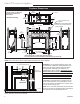
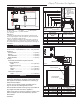
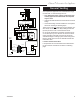
Locating Your Fireplace
LU584-1
Fig. 1 Locate gas fireplace.
A) Flat on wall B) **Island C) *Room divider
D) *Flat on wall corner E) Chase installation
Y) 6” minimum
Note (Fig. 1):
** Island (C) and Room Divider (D) installation is possible as long
as the horizontal portion of the vent system (X) does not exceed 20’
(610cm). See details in Venting Section.
* When you install your fireplace in (D) Room divider or (E) Flat on
wall corner positions (Y), a minimum of 6” (152mm) clearance must
be maintained from the perpendicular wall and the front side edge of
the fireplace.
Top of Unit to Ceiling ................................ 36” (914 mm)
Front of Unit to Combustibles (both sides) ... 36” (914 mm)
Appliance
Top Standoffs .............................................. 0” (0 mm)
Bottom ......................................................... 0” (0 mm)
Side Standoffs ............................................. 0” (0 mm)
Back Standoffs ............................................ 0” (0 mm)
Venting
Horizontal Termination through-a-side wall:
Vertical Sections:
Sides ................................................ 2¹⁄₂” (64 mm)
Horizontal Sections:
Top .................................................. 3¹⁄₂” (89 mm)
Bottom ............................................. 1¹⁄₂” (38 mm)
Sides ................................................ 2¹⁄₂” (64 mm)
Vertical Vent Application:
Sides ............................................... 1¹⁄₂” (38 mm)
Clearance to Combustibles
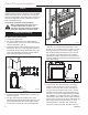
Mantels
The height that a combustible mantel is fitted above the
fireplace is dependent on the depth of the mantel. This
also applies to the distance between the mantel leg (if
fitted) and the fireplace.
For the correct mounting height and widths refer to
Figs. 3a and 3b, the following Mantel Charts.
Noncombustible mantels and legs may be installed at
any height and width around the appliance.
When using paint or lacquer to finish the mantel, such
paint or lacquer must be heat resistant to prevent
discoloration.
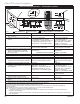
Fig. 3a Combustible mantel minimum installation.
Mantel Chart
Mantel Shelf Mantel from Top
Ref. or Breast Plate Ref. of Comb. Chamber
Depth
V 10” (254 mm) A 10” (254 mm)
W 9” (229 mm) B 9” (229 mm)
X 8” (203 mm) C 8” (203 mm)
Y 7” (178 mm) D 7” (178 mm)
Z 6” (152 mm) E 6” (152 mm)
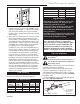
CFM146d
Combustible
Framing and
Finish Wall Above
Standoffs
Standoff
Top of Sheet Metal
Noncombustible Finish Material
(Such as Dura Rock)
Fireplace Front
May use com-
bustible facing
material in this
area
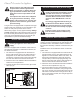
Mantel Leg
CFM164c
CFM170a
Fig. 3b Combustible mantel leg minimum installation.
Mantel Mantel Leg from Side
Ref. Leg Depth Ref. of Comb. Opening
F 12” (305 mm) K 12” (305 mm)
G 9” (229 mm) L 9” (229 mm)
H 6” (152 mm) M 6” (152 mm)
I 4” (102 mm) N 4” (102 mm)
J 3” (76 mm) O 3” (76 mm)
Side of Fireplace
Noncombustible
Finish Material