
Specifications
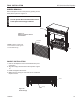
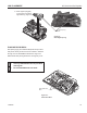

DFS Series Vent Free Fireplace
14
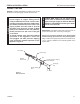
71D0532
FP2449
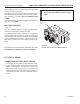
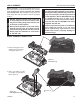
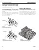
install remote receiver
Remote
Receiver
FP2449
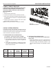
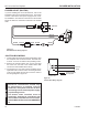
The millivolt system and individual components may be
checked with a millivolt meter having a 0-1000 mV range.
Conduct each check shown in chart below by connection
meter test leads to terminals as indicated.
a. If the reading is more than 100 millivolts and the
automatic valve still does not come on, replace the
control.
b. If the closed circuit reading (“A” reading) is less than
100 millivolts, determine cause for low reading, pro-
ceed to Section B below.
A Complete 2 & 3 Closed Closed
System
B Thermopile 1 & 2 Open Open
THESE INSTRUCTIONS SUPERCEDE THE SECTION
ENTITLED “HEARTH MOUNT” IN THE
HAND-HELD REMOTE INSTRUCTIONS SUPPLIED
WITH THE REMOTE.
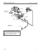
Figure 12
1. Remove bottom louvre door.
2. Connect the remote connectors located in the unit.
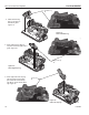
3. Stick Velcro• pads with self-adhesive backing to bottom
of remote receiver and to oor of compartment behind
access panel.
4. Attach remote receiver to rebox with Velcro• pads.
Control switch must face forward.
Do not place remote in combustion chamber.
1. Check gas pressure to the unit. If gas pressure is
within minimum and maximum on data plate, then
check pilot voltage, 325 millivolts minimum. If the
minimum millivolt reading is not obtainable, replace
pilot.