
- CFM Specialty Indoor Fireplace User Manual


6
10005360
Vermont Castings, Majestic Products LHE Natural Vent Insert
Natural LP
Minimum Inlet Pressure 5.5" W.C.11.0" W.C.
Maximum Inlet Pressure 14.0" W.C. 14.0" W.C.
Manifold Pressure 3.5" W.C. 10.0" W.C.
Gas Inlet & Manifold Pressures
Do not use this appliance if any part of it
has been under water. Immediately call a
qualified service technician to inspect the
unit and replace any part of the control
which has been under water.
LHEC20 / LHER20 / LHEC30
Certified To
ANSI Z 21.88-2002 / CSA 2.33-2002
Vented Gas Fireplace Heaters
Preparation
Before beginning, remove glass door and logs from
unit. Also check to make sure there is no hidden
damage to the unit. Take a minute and plan out the
gas,venting and electrical route. It is best to start with
the gas line first followed by the chimney liner. (Refer to
Page 9)
Gas Line Installation
When purging the gas line, the front
glass must be removed.
If gas piping from the source to the heater location has
not been accomplished, install the required pipe.
Consult local plumbing code to assure proper pipe size.
The gas pipeline can be brought in through the rear or
the base of the heater.
NOTE: The gas line connection can be made of either
properly tinned 3/8" copper tubing, 1/2" rigid pipe or an
approved flex connector then reduced to 3/8" to the
heater. Some municipalities have additional local
codes, it is always best to consult your local authority
and the CSA- B149.1 installation code.
U.S. Installations consult the current National Fuel
Gas Code, ANSI Z223.1
Always check for gas leaks with a mild
soap and water solution. Do not use an
open flame for leak testing.
The gas control is equipped with a captured screw type
pressure test point, therefore it is not necessary to
provide a 1/8" test point up stream of the control.
When using copper or flex connector, use only
approved fittings. Always provide a union when using
black iron pipe so the gas line can be easily
disconnected for burner or fan servicing. See gas
specifications for pressure details and ratings. NOTE:
If flex connector is used, it must be kept inside of the
heater.
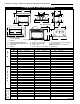
Gas Specifications
Max. Min.
Input Input
Model Fuel Gas Control Btu/h Btu/h
LHEC20RN Natural Gas Millivolt Hi/Lo 20,000 14,000
LHEC20RP Propane Gas Millivolt Hi/Lo 20,000 15,000
LHEC20RFN Natural Gas Comfort Control 20,000 14,000
LHEC20RFP Propane Gas Comfort Control 20,000 15,000
LHER20RN Natural Gas Millivolt Hi/Lo 20,000 14,000
LHER20RP Propane Gas Millivolt Hi/Lo 20,000 15,000
LHEC30RN Natural Gas Millivolt Hi/Lo 30,000 21,000
LHEC30RP Propane Gas Millivolt Hi/Lo 30,000 22,500
LHEC30RFN Natural Gas Comfort Control 30,000 21,000
LHEC30RFP Propane Gas Comfort Control 30,000 22,500
These gas inserts are approved for installation in
solid fuel burning masonry or zero clearance
fireplaces.
High Elevations
Input ratings are shown in BTU per hour and are
certified without deration for elevations up to
4,500 feet (1,370m) above sea level.
For elevations above 4,500 feet (1,370m) in USA,
installations must be in accordance with the
current ANSI Z223.1 and/or local codes having
jurisdiction.
In Canada, please consult provincial and/or local
authorities having jurisdiction for installations at
elevations above 4,500 feet (1,370m).
1/2" Gas Supply
1/2" x 3/8" Shut Off Valve
3/8" Nipple
3/8" Union
FP297
Fig. 4 Typical gas supply installation.
3/8"
Nipple