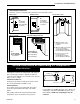
INSTALLER/CONSUMER SAFETY INFORMATION Builder Rear Vent Direct Vent PLEASE READ THIS MANUAL BEFORE INSTALLING AND USING APPLIANCE Model: H33BDVRRN/P WARNING! IF THE INFORMATION IN THIS MANUAL IS NOT FOLLOWED EXACTLY, A FIRE OR EXPLOSION MAY RESULT CAUSING PROPERTY DAMAGE, PERSONAL INJURY OR LOSS OF LIFE. FOR YOUR SAFETY Installation and service must be performed by a qualified installer, service agency or the gas supplier. WHAT TO DO IF YOU SMELL GAS: • Do not try to light any appliance.
Pyromaster© H33BDVRRN/P Table of Contents Please read the installation & operating instructions before using appliance Thank you and congratulations on your purchase of a CFM Harris Systems fireplace. IMPORTANT: Read all instructions and warnings carefully before starting installation. Failure to follow these instructions fully may result in a possible fire hazard and will void the warranty. Installation & Operating Instructions ..............................................................................
Pyromaster© H33BDVRRN/P Installation & Operating Instructions This gas appliance should be installed by a qualified installer in accordance with local building codes and with current CSAB149.1 Installation codes for Gas Burning Appliances and Equipment. For USA Installations follow local codes and/or the current National Fuel Gas Code. ANSI Z223.1. FOR SAFE INSTALLATION AND OPERATION PLEASE NOTE THE FOLLOWING: 1 .
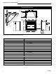
Pyromaster© H33BDVRRN/P Fireplace Dimensions Rough Opening Depth E M P F M Q - Rough Opening Width O N B Rough Opening Height G I R D C H A J K L 4758 Fig. 2 Fireplace specifications and framing dimensions. Ref.
Pyromaster© H33BDVRRN/P Clearance to Combustibles Appliance Top.............................................. 0” (0 mm) Bottom........................................ 0” (0 mm) Side............................................ 0” (0 mm) Back........................................... 0” (0 mm) Venting Concentric sections of DV Vent Top, bottom & sides.................. 1” (25 mm) Rear Vent Applications: Top............................................ 2” Sides.........................................
Pyromaster© H33BDVRRN/P Framing and Finishing Gas Specifications 1. Choose the unit location. 2. Place the unit into position and secure it to the floor with 1¹⁄₂” (38mm) screws, or nails. The holes to secure the unit to the floor are located just behind the access door grille on the left and right side of the unit. 3. Frame in the fireplace with a header across the top. It is important to allow for the finished wall face when setting the depth of the frame. 4.
Pyromaster© H33BDVRRN/P Remote ON/OFF Switch 1/2” Gas Supply TPTH 1/2” NPT x 1/2” Flare Shut-Off Valve 3/8” Flex Line (From Valve) TP TH FP297a FP1218 Fig. 5 Typical gas supply installation. Always check for gas leaks with a mild soap and water solution. Do not use an open flame for leak testing. The gas control is equipped with a captured screw type pressure test point, therefore it is not necessary to provide a 1/8" test point up stream of the control.
Pyromaster© H33BDVRRN/P General Venting Information - Termination Location INSIDE CORNER DETAIL G V H A D V N N E V B C V L B Fixed Closed Ope F B V Operable rab V le V Fixed Closed G V B B B V J X I A V VENT TERMINATION M G V K X V A X AIR SUPPLY INLET AREA WHERE TERMINAL IS NOT PERMITTED CFM145a Canadian Installations1 A = Clearance above grade, veranda, porch, deck, or balcony B = Clearance to window or door that may be opened C = Clearance to permanently closed w
Pyromaster© H33BDVRRN/P Termination Clearances Termination clearances for buildings with combustible and noncombustible exteriors. Inside Corner Recessed Location Outside Corner A= Combustible 6"(152mm) Noncombustible 2"(50mm) A V B= Combustible 6"(152mm) Noncombustible 2"(50mm) V D C C E V B Balcony with perpendicular side wall Balcony with no side wall G V V G= Combustible& Noncombustible 12"(305mm) C = Maximum depth of 48" (1219mm) for recessed location.
Pyromaster© H33BDVRRN/P Twist Lock Pipes To join the twist lock pipes together, simply align the beads of the male end with the grooves of the female end, then while bringing the pipe together, twist the pipe until the flange on the female end contacts the external flange on the male end. It is recommended that you secure the joints with three (3) sheet metal screws, however this is not mandatory with twist lock pipe.
Pyromaster© H33BDVRRN/P Top View Straight Venting 20" (508mm) Max. Combustible Walls: Cut a 10³⁄₈”H (264 mm) x 9³⁄₈” W (240 mm) hole through the exterior wall and frame as shown. (Fig.13) Noncombustible Walls: Hole opening must be 7¹⁄₂” (190 mm) in diameter. (Fig. 13) STEP 2 20" (508mm) Max. Measure wall thickness and cut zero clearance sleeve parts to proper length (MAXIMUM 12”/305 mm). Assemble sleeve and attach to firestop with #8 sheet metal screws (supplied). 20" (508mm) Max. Max.
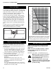
Pyromaster© H33BDVRRN/P STEP 5 Guide the vent termination 4” collar into the 4” pipe then the 7” collar into the 7” pipe. Do not force the venting into position. If the pipes do not line up with the termination collars, disassemble pipes and reattach to the fireplace collar. (Fig. 16) STEP 6 Horizontal plane means no vertical rise exists on this portion of the vent assembly. • The maximum horizontal vent run is 20 ft. (6100 mm) when the vertical vent rise is 7¹⁄₂ ft. (2286 mm). (Fig.
Pyromaster© H33BDVRRN/P Example: According to the chart the maximum horizontal vent length in a system with a 7.5' vertical rise is 20' (6 m) and if a 90° elbow is required in the horizontal vent it must be reduced to 17' (5.2 m). In Figure 20 Dimension A plus B must not be greater than 17' (5.2 m). 7 ft. (2134 mm) A B 10 ft. (3048 mm) • IMPORTANT • Minimum clearance between vent pipes and combustible materials is one (1”) inch (25 mm) on bottom, sides and top.
Pyromaster© H33BDVRRN/P STEP 2 STEP 4 Measure wall thickness and cut adjustable zero clearance sleeve parts to proper length (MAXIMUM 12”/305 mm). (Fig. 22) Adjust sleeve to minimum (9³⁄₈” x 9³⁄₈”) and attach to firestop with #8 sheet metal screws (supplied). Assemble sleeve and attach to firestop with #8 sheet metal screws (supplied). Install firestop assembly. Measure the horizontal length requirement including a 2” (50 mm) overlap, i.e.
Pyromaster© H33BDVRRN/P STEP 6 Apply high temperature sealant to 4” (100 mm) and 7” (175 mm) collars or the termination one inch away from the crimped end. Guide the vent termination’s 4” and 7” collars into their respective vent pipes. Double check that the vent pipes overlap the collars by 2” (50mm). Secure the termination to the wall with screws provided and caulk around the wall plate to weatherproof. (Fig.
Pyromaster© H33BDVRRN/P If the foundation is recessed, use recess brackets (not supplied) for securing lower portion of the snorkel. Fasten brackets to wall first, then secure to snorkel with self drilling #8 x 1/2 sheet metal screws. It will be necessary to extend vent pipes out as far as protruding wall face. (Fig. 28) Example: Maximum horizontal length 0 x 45° elbows = 10’ (3048mm) 1 x 45° elbows = 8¹⁄₂’ (2590mm) 2 x 45° elbows = 7’ (2133mm) c. A minimum of an 8’ vertical rise. d.
Pyromaster© H33BDVRRN/P 6. Place firestop(s) #7DVFS or Attic Insulation Shield #7DVAIS into position and secure. (Fig. 31) 7. Install roof support (Fig. 32) and roof flashing making sure upper flange is below the shingles. (Fig. 33) 8. Install appropriate pipe sections until the venting is above the flashing. (Fig. 33) 9. Install storm collar and seal around the pipe. 10. Add additional vent lengths for proper height. (Fig 34) 11.
Pyromaster© H33BDVRRN/P Twist Lock Venting Components 7TDVRVT-Through the wall Rear Vent Termination Starter Kit-Model7TDVSK-Sidewall Venting Starter Kit-Model 7TDVSKV-Vertical Venting for 7TDVSKV-A order 1/12 to 6/12 roof pitch for 7TDVSKV-B order 7/12 to 12/12 roof pitch for 7TDVSKV-F order flat roof Starter Kit-Model 7DVSKS-Snorkel Kit for Below Grade Installation 45° elbow kit 7TDV45 for Rear Vent to Vertical Vent or Vertical/Horizontal Offsets 90° Transition elbow kit 7TDVRT90 for Rear Vent to Vertic
Pyromaster© H33BDVRRN/P Crimped End Venting Components 7TDVRVT-Through the wall Rear Vent Termination Starter Kit-Model 7TDVSK-Sidewall Venting Starter Kit-Model 7TDVSKV-Vertical Venting for 7TDVSKV-A order 1/12 to 6/12 roof pitch for 7TDVSKV-B order 7/12 to 12/12 roof pitch for 7TDVSKV-F order flat roof Starter Kit-Model 7DVSKS-Snorkel Kit for Below Grade Installation 45° elbow kit 7DVT45 for Vertical Installation Offsets 7DVR45 for Rear Vent Application 90° Transition elbow kit 7DVRT90 for Vertical Sid
Pyromaster© H33BDVRRN/P Operating Instructions Glass Information • Only glass approved by the CFM Corporation should be used on this fireplace. The use of any non-approved replacement glass will void all product warranties. • Care must be taken to avoid breakage of the glass. • Under no circumstances should this appliance be operated without the window frame assembly in place, or with the glass in a damaged condition.
Pyromaster© H33BDVRRN/P Log Identification Chart H33BDVRRN/P BA9 BA7 BA8 For units equipped with ‘HI/LO’ valves the flame adjustment is accomplished by rotating the ‘HI/LO’ adjustment knob located near the center of the gas control valve. (Fig. 38) Refer to Figure 37 1. Remove the top louvre assembly. 2. Remove the window frame assembly. 3. Fit the rear front right log (BA8) onto the rear log support.
Pyromaster© H33BDVRRN/P Lighting And Operating Instructions FOR YOUR SAFETY READ BEFORE LIGHTING WARNING:If you do not follow these instructions exactly, a fire or explosion may result causing property damage, personal injury or loss of life. A. This heater has a pilot which must be lit manually. When lighting the pilot follow these instructions exactly. B. BEFORE LIGHTING smell all around the heater area for gas.
Pyromaster© H33BDVRRN/P Troubleshooting – Honeywell VS8421 Remove Glass Doors Before Service Work CHECK GAS SUPPLY ON NO ▼ START • Supply Line Hooked Up • Shutoff Valve Open YES • Lockout Has Engaged. Wait 60 Seconds And Try Again. PILOT LIGHTS WITH PIEZO IGNITOR NO ▼ ▼ • For Spark At Electrode While • • YES • For Air In The Lines • Thermopile Needs A Min. NO ▼ ▼ PILOT STAYS LIT • • • • YES 325mv. Adjust Pilot Flame Height.
Pyromaster© H33BDVRRN/P This unit is factory setup for use with natural gas. The conversion of this appliance from natural gas to propane gas must be carried out by an authorized service provider. LP Conversion Kit Components (Supplied with unit.) Description Pilot Orifice #35 Main Burner Orifice #56 Honewell Conversion Kit Part # 10002269 50999 20000550 LP Conversion Procedure 24 Air Shutter Setting The air shutter is factory set at 50% open for natural gas (or if converting back to natural gas).
Pyromaster© H33BDVRRN/P Maintenance Burner and Burner Compartment FK24/FK12 Fan Assembly It is important to keep the burner and the burner compartment clean. At least once per year the logs and lava rock/ember material should be removed and the burner compartment vacuumed and wiped out. Remove and replace the logs as per the instructions in this manual. The optional fan unit requires periodic cleaning.
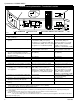
Pyromaster© H33BDVRRN/P 7 1 5 3a/b 6 4 1b 1c 2 1a 10 8 OFF 13 O H PILOT ADJ ON P IL O T L I 9a/b 11 15 17 14 18 12 16 4758 CFM Harris Systems reserves the right to make changes in design, materials, specifications, prices and discontinue colors and products at any time, without notice. H33BDVRRN/P Ref. 1. 1a. 1b. 1c. * * 2. * * 3a. 3b.
Pyromaster© H33BDVRRN/P H33BDVRRN/P (continued) Ref. 4. * * 5. 6. 7. 8. * * 9a. 9b. 10. * * * * 11. 12. * * 13. 14. 15. 16. 17. * * * 18. * Description Pilot, Top Convertible SIT Pilot Orifice - SIT Top Convertible Nat. (not shown) Pilot Orifice - SIT Top Convertible Prop.
Pyromaster© H33BDVRRN/P Optional Accessories Available Fan Kits Thermal Sensor Fan FK24 Fan Assembly This auxiliary fan system increases the efficiency of the circulation of the heated air. The FK24 fan kit allows variable speed control of the circulation fan and also incorporates a heat sensor in the circuit. Specifications 115 Volts / 60Hz / 56 Watts Maintenance The fan itself does not require regular maintenance, however periodic cleaning of the fan and the surrounding area is required.
Pyromaster© H33BDVRRN/P Wiring Instructions The fireplace, when installed, must be electrically connected and grounded in accordance with local codes or, in the absence of local codes, with the current CSA C22.1 Canadian Electric Code. For USA installations follow the local codes and the national electrical code ANSI/NFPA No. 70. Should this fan require servicing or repair the power supply must be disconnected. For rewiring of any replacement parts refer to Figure 43.
Pyromaster© H33BDVRRN/P 4. Lay the angular base panels in place on the floor of the firebox on either side of the burner housing assembly. 5. Loosely attach the top adjustable tabs to the studs located in the top of the firebox toward the front corners. 6. Place the rear refractory panel in place. Locate the lower edge of the panel in the ledge formed by the top of the rear log support bracket. 7. Slide the side refractory panels into place to hold the rear panel secure.
Pyromaster© H33BDVRRN/P Bay Window Screen Remote Controls A Bay Window Screen Kit is available for the H33BDVRRN/P. Optional remote control units are available to control different functions of the appliances. Do not remove existing window frame assembly! Remove all plastic from brass trims. 1. Let the fireplace cool down if it has been operating. 2. Remove existing top louvre from fireplace by lifting up and pulling out. 3. Hang Bay Window Screen assembly over top of the existing glass frame.
LIMITED WARRANTY & EXTENDED LIFE TIME PROTECTION For Pyromaster® Gas Appliance Products* BASIC WARRANTY: CFM Harris Systems (hereinafter referred to collectively as the "Company") warrants that your new Pyromaster Gas Appliance is free from manufacturing and material defects for a period of one year from date of installation, subject to the following conditions and limitations.