EWF30 Fireplace Homeowner’s Installation and Operating Manual SAFETY NOTICE: IF THIS APPLIANCE IS NOT PROPERLY INSTALLED, OPERATED AND MAINTAINED, A HOUSE FIRE MAY RESULT. TO REDUCE THE RISK OF FIRE, FOLLOW THE INSTALLATION INSTRUCTIONS. FAILURE TO FOLLOW INSTRUCTIONS 8662 MAY RESULT IN PROPERTY DAMAGE, BODILY INJURY OR EVEN DEATH. CONTACT LOCAL BUILDING OFFICIALS ABOUT RESTRICTIONS AND INSTALLATION EWF30 cover INSPECTION REQUIREMENTS IN YOUR AREA.
Vermont Castings EWF30 Introduction Thank you for purchasing a Vermont Castings, EWF30 fireplace. An efficient fireplace carefully engineered to bring you the latest in wood combustion principles and modern foundry technology. You can count on years of comfortable heating and pleasurable fire viewing if you treat it properly and operate the EWF30 according to the directions in this owner’s guide.
Vermont Castings EWF30 Safety Information Please Read This Manual Before Installing and Using Fireplace IMPORTANT: Read all instructions and warnings carefully before starting installation. Failure to follow these instructions may result in a possible fire hazard and will void the warranty. Description The EWF30 fireplace is a clean burning, non-catalytic, EPA certified solid fuel, wood burning, heat circulating fireplace. Precautions This fireplace and chimney system must be vented to the out-of-doors.
Vermont Castings EWF30 Specifications EWF30 Range of heat output* ............... 11,100 - 40,500 Btu/hr Maximum heat output** ....... in excess of 55,000 Btu/hr EPA emissions rating (g/h) ......................................3.5* Area heated*** .............. Up to 2,400 sq. ft. (223 sq. m) Size of wood splits ....................18” - 23” (457-584 mm) Fuel Capacity .......................................... 40lbs. (18 kg) Loading ..................................................................
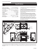
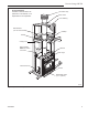
Vermont Castings EWF30 Chase Installation Insulation methods shown are optional for cold climate, not a requirement for unit operation. Termination Cap Storm Collar Pan Flashing Batt Insulation (cut out around firestop) Draftstop Firestop Ceiling Level Batt Insulation MUST be used in the Chase. Standoff Brick Ledge Electrical Access Andiron Metal Safety Strips (1,2 or 3 pieces) FP1561 Fig. 2 Fireplace and chase parts identification.
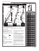
Vermont Castings EWF30 Chimney Requirements - Offset Installations Offset CHIMNEY FLUE EXIT Rise Chimney Section D E 6 FT. C G 30° Offset Elbow Rise Offset H 30° Return Elbow 30° Offset Elbow B G TCS8A Support H Hearth Floor Example 1 Example 2 Example 3 Notes: G + H cannot exceed 20 feet. FP269 Air Space Clearances: “SK” Series (2-wall) = 1¹⁄₂” Min. to Combustibles “S” Series (3-wall) = 2” Min.
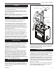
Vermont Castings EWF30 Planning Information Planning an installation is very important to ensure safety and to save time and money. An installer must predetermine where a fireplace will be set and how the chimney system will be run. Mounting the Fireplace The fireplace is shipped with lifting handles attached to each side with lifting straps. NOTE: The lifting straps are intended for ligting unit off of the skid and final positioning. Unit should remain on skid until final positioning.
Vermont Castings EWF30 Installation Chimney Supports The chimney system is supported by the fireplace for vertical chimney heights less than 30’ (9m) above the hearth. Chimney supports are required if the vertical height exceeds 30’ (9m). Locate chimney supports at ceiling holes or other structural framing at 30’ (9m) heights. Spacing between chimney supports must not exceed 30’ (9m). Use Chimney Support Model SKCS8. (NOTE: The SKCS8 cannot be mounted directly to the fireplace.
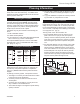
Vermont Castings EWF30 Framing Framing can be constructed before or after the fireplace is set in place, however, most installers build the frame before setting the fireplace. Frame fireplace with 2 x 4 lumber or heavier materials. Refer to framing dimensions in Figure 1 for basic fireplace specifications. Chimney Centerline Actual Centerpoint 9���" (241mm) NOTE: Framing should be positioned to accommodate wall covering and fireplace facing material.
Vermont Castings EWF30 Locate center point of the chimney on ceiling as though a straight up chimney arrangement is to be used. Measure your offset dimension from straight up chimney center point on ceiling. Existing Ceiling Joists AB AB Chimney Hole Ceiling Chimney Hole/ Possible Obstructions The size of the hole in ceiling will vary with the angle at which the chimney passes through ceiling. Drive a nail up through ceiling at marked chimney center point.
Vermont Castings EWF30 Nail Top Standoffs Nail Side Nailing Flanges of the duct termination and the route of the duct run between the fireplace and the duct termination. Duct run must be limited to a maximum distance of 40 feet from the fireplace pipe collar to duct termination. This will provide the least restriction to air flow. No more than four (4) 90° elbows can be used. Duct run may be horizontal, vertical, inclined or any combination of these.
Vermont Castings EWF30 Installing the Chimney System Outside Air Opening Start by attaching the first chimney section to the collar on top of the fireplace. Install the pipe as pictured in Figure 16. When you get a good lock, you will hear the pipe clearly snap together. Once sections are snap-locked in place, it is extremely difficult to get them apart. Make sure the pipe is firmly snapped and locked together as each pipe section is mounted. Air Inlet Opening FP1592 Fig.
Vermont Castings EWF30 Installing the Firestop Spacer in the Ceiling Hole Canadian Requirements for Insulation Shield A firestop spacer is used to keep pipe spaced properly and required for safety. Nail the firestop spacer (at each corner) to the framing members of the ceiling hole. NOTE: A firestop spacer is not required at the roof. Hole sizes listed in Figure 9 for angled firestop spacers provide minimum required air space to chimney pipe for ceiling thickness up to 8” (203mm).
Vermont Castings EWF30 Penetrating the Roof Run pipe to roofline. Since chimney system must be vented to the out-of-doors, you must use an approved CFM Corporation termination. If a chase is used, refer to the installation manual provided with the termination cap. CAUTION: Treatment of firestop spacers and construction of chase may vary with type of building. These instructions are not a substitute for local building codes.
Vermont Castings EWF30 local building codes for minimum clearance from top of fireplace opening to bottom of mantel shelf. All joints (top, bottom and sides) where wall or decorative facing material meets fireplace surround must be completely sealed with a noncombustible material. (Figures 21 and 25) Combustiible Mantel and Trim Header Standoff 12" (305mm) Min. Side View Noncombustible Material 6" (159mm) Min.
Vermont Castings EWF30 Side Wall Protection Adjacent combustible side walls that are within minimum dimensions shown in Figure 25 of the fireplace opening must be protected with CFM Corporation Wall Shield Model SP40 or a specifically built wall shield described in Figure 20. The special wall shield design described in Figure 20 is an alternate method of adding protection to side walls and can be used in place of the SP40 with the same wall clearances specified for the SP40. Rt must =1.85 minimum.
Vermont Castings EWF30 Minimum Hearth Extension Dimensions Minimum Wall Clearances WITH Noncombustible Surround Facing WITHOUT Noncombustible Surround Facing Shaded area starts 1/2" away from edge of unit 4" Brick (Example material) 4" E F** C** Firebox Opening E NOTE: No material may cover black cast face. Hearth extension must be flush with bottom of fireplace. H G G J D A - Min. clearance to combustible perpendicular wall B - Min.
Vermont Castings EWF30 Operation Attach Handles The fallaway handle is used to open and close the front doors. Remove after each use so the handle will not get hot. Keep in convenient location for each use. (Fig. 27) Primary Air Control Damper Assemble the primary air control and damper handles by passing the screw through the wood shaft and into the bright metal hub. Tighten carefully until snug. Do not overtighten. Wood handle could crack. (Fig. 28) Steel Handle Fallaway Handle FP1570 Fig.
Vermont Castings EWF30 The Fan Heated air from the fireplace is forced into the room by an internal fan. The control for the fan is in the right corner of the unit. “Off” is to the far left. (counterclockwise “High” is just to the right of “Off.” “Low” is to the far right. (clockwise ) ) Variable adjustment of the fans is possible with any setting between “high” and “low.” For best results, coordinate fan speed with the setting of the primary air control.
Vermont Castings EWF30 Starting and Maintaining a Wood Fire Burn solid wood fuel only in the EWF30, and burn it directly on the grate. Do not elevate the fuel. Do not burn coal or other fuels. Minimize thermal stress by allowing the plates to adjust gradually during an initial break-in fire by following Steps 1-3 below. WARNING: Operate your EWF30 only with the doors fully closed. If the door is left partially open, gas and flame may be drawn out of the fireplace opening, creating risks of both fire and smoke.
Vermont Castings EWF30 A well-insulated home, located in a moderate climate and with the EWF30 Fireplace located centrally in an open floor plan, will be easier to heat than a drafty home in the far north in which the EWF30 is installed on an exterior wall at the end of a long house. • Different results may be experienced even in the same installation if you switch from burning good, dry wood to wood that is partially rotted or inadequately seasoned.
Vermont Castings EWF30 Maintenance Keep your EWF30 Fireplace Looking New and Working Its Best Care of the Cast Iron Surface An occasional dusting with a dry rag will keep your EWF30 fireplace looking new. If the paint needs retouching, first allow the surface to cool completely. Wire-brush areas needing to be painted. Touch-up with high temperature fireplace paint available from your local dealer. Apply the paint sparingly. Two light coats are better than one heavy one.
Vermont Castings EWF30 1. Remove the existing fiberglass gasket by grasping an end and pulling firmly. The Chimney System 2. Use a wire brush or the tip of a screwdriver to clean the channel of any remaining cement or bits of gasket. 3. Apply a thin bead of fireplace cement to the newlycleaned groove. 4. Pack a new gasket into the groove. Wait until you have placed all but a couple inches from the end before you trim the end to an exact fit. A Clean Chimney System is Safer and Works Better 5.
Vermont Castings EWF30 The prefabricated chimney used with your fireplace should be cleaned from above using an 8” round brush and the appropriate number of extension rods for complete access. The chimney cap first must be removed following the procedure recommended by the manufacturer. After thoroughly cleaning the chimney, reinstall the chimney cap according to the manufacturer’s directions. Maintenance Schedule Fireplace: Daily: • Ash should be removed before the level reaches the top of the pan.
Vermont Castings EWF30 Chimney Components Component U.S. Round Top Termination Round Top Termination Extended Flashing Square Termination Housing Adapter Kit Housing Extensions Square Chase Termination Adapter Kit Chase Top Housing Chase Top Housing SK8 Chimney Sections SK8 Chimney Elbows Firestop Chimney Support Attic Insulation Shield Canada Chimney Collar Enclosure Attic Insulation Shield SK8 Chimney Sections 45˚ Chimney Elbows 20008662 Description Top used to terminate chimney at roof.
Vermont Castings EWF30 30, 31 4 35 36 18 40 51 34 47 39 44,45,46 23 38 41,42,43 20 28 27 37 26 22 25 17 24 50 19 20 50 8 13 11,12, 32,33 52 19 15 17 3 14 8 16 1 7 5 49 21 10 6 2 9 CFM Corporation reserves the right to make changes in design, materials, specifications, prices and discontinue colors and products at any time, without notice. EWF30 Fireplace For unit WFE05H0 Ref. 1. 2. 3. 4. 5. 6. 7. 8. 9. 10. 11. 12. 13. 14. 15.
Vermont Castings EWF30 EWF30 Fireplace Ref. 16. 17. 18. 19. 20. 21. 22. 23. 24. 25. 26. 27. 28. 29. 30. 31. 32. 33. 34. 35. 36. 37. 38. 39. 40. 41. 42. 43. 44. 45. 46. 47. 48. 49. 50. 51. 52. (continued) Description Grate, Flat/Wood Firebrick, Split Bracket, Actuator Brick Retainer Brick Retainer Door Gasket 1/2” Dia.
Vermont Castings EWF30 Optional Accessories Fan Kit FK26 Fan The FK26 fan helps distribute heated air from within the firebox out into the room. The fan is controlled by a snapstat that turns power on and off as the firebox temperature rises above and falls below a preset temperature. A rheostat provides for variable fan speeds. Specifications 115 Volt / 60Hz / .75 Amps Maintenance The fan itself does not require regular maintenance, however, periodic cleaning of the fan and the surrounding area is required.
Vermont Castings EWF30 Trim Kits A choice of two decorative stell face plates with brick ledge for masonry applications (if needed) are available to enhance the look of your EWF30 fireplace. Installation instructions are included with the kit. Model EWF30SFP EWF30SFD Description Steel Face Plate Decorative Steel Face Plate EWF30SFP EWF30SFD FP1579 Fig. 33 Decorative steel face plates.
Vermont Castings EWF30 30 20008662
LIMITED LIFETIME Warranty Vermont Castings EWF30 For Vermont Castings EWF30, Sequoia II, Non-Catalytic Woodburning Fireplace Limited Lifetime Warranty CFM Corporation warrants that all refractory brick and material used in this product will be warranted against deterioration not resulting from physical damage or overloading of the wood fireplace for the lifetime of this product. This coverage includes the components of the EverBurn System: “shoe, fountain, and fireback.
CFM Corporation 2695 Meadowvale Blvd. • Mississauga, Ontario, Canada L5N 8A3 800-668-5323 • www.cfmcorp.