INSTALLER/CONSUMER SAFETY INFORMATION PLEASE READ THIS MANUAL BEFORE INSTALLING AND USING APPLIANCE WARNING! IF THE INFORMATION IN THIS MANUAL IS NOT FOLLOWED EXACTLY, A FIRE OR EXPLOSION MAY RESULT CAUSING PROPERTY DAMAGE, PERSONAL INJURY OR LOSS OF LIFE. FOR YOUR SAFETY Installation and service must be performed by a qualified installer, service agency or the gas supplier. Chateau™ Direct Vent Gas Fireplace Model: DVT38S2IN WHAT TO DO IF YOU SMELL GAS: • Do not try to light any appliance.
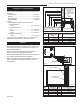
Chateau™ Direct Vent Gas Fireplace Table of Contents Please read the installation & operating instructions before using this appliance. Thank you and congratulations on your purchase of a CFM Corporation fireplace. IMPORTANT: Read all instructions and warnings carefully before starting installation. Failure to follow these instructions may result in a possible fire hazard and will void the warranty. Installation & Operating Instructions Important Curing/Burning Instructions ..................................
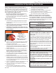
Chateau™ Direct Vent Gas Fireplace Installation & Operating Instructions This gas fireplace should be installed by a qualified installer, preferably NFI or WETT (Canada) certified, in accordance with local building codes and with current CSAB149.1 Installation codes for Gas Burning Appliances and Equipment. For USA Installations follow local codes and/or the current National Fuel Gas Code. ANSI Z223.1/NFPA 54.
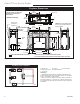
Chateau™ Direct Vent Gas Fireplace Fireplace Dimensions Finished Wall 24¹⁄₂” (622 mm) for Flush Install 16” (406 mm) I.D.
Chateau™ Direct Vent Gas Fireplace Combustible Framing and Finish Wall Above Standoffs May use combustible facing material in this area Standoff Clearance to Combustibles Top of Unit to Ceiling ................................ 36” (914 mm) Front of Unit to Combustibles (both sides) 36” (914 mm) Appliance Top Standoffs .............................................. 0” (0 mm) Bottom* ....................................................... 0” (0 mm) Side Standoffs .............................................
Chateau™ Direct Vent Gas Fireplace Hearth A hearth is not mandatory but is recommended for aesthetic purposes. We recommend a noncombustible hearth which projects out 12” (305 mm) or more from the front of the fireplace. The hearth cannot exceed 1¹⁄₂” (38 mm) in height from bottom of fireplace for ease of door accessibility. (Fig.
Chateau™ Direct Vent Gas Fireplace Gas Inlet and Manifold Pressures Minimum Inlet Pressure Maximum Inlet Pressure Manifold Pressure 1/2” NPT X 1/2” Flare Shut-off Valve Natural LP (Propane) 5.5” w.c. 11.0” w.c. 14.0” w.c. 14.0” w.c. 3.5” w.c. 10.0” w.c. High Elevations Input ratings are shown in BTU per hour and are certified without deration for elevations up to 4,500 feet (1,370m) above sea level.
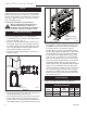
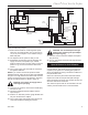
Chateau™ Direct Vent Gas Fireplace Control System The gas control system is located on the right hand side of the firebox behind an access panel and the decorative brick panel. The fireplace is operated using only the hand held remote control unit. The system wiring diagram is shown in Figure 11. NOTE: If you choose to install the battery back-up, Model DVTBBK, refer to Item #16 in the next section. Gas Supply Fitting Pressure Test Ports Learn Button Control System Installation 1.
Chateau™ Direct Vent Gas Fireplace White or Green Green or White White or Orange Orange or White To Pilot Ignitor Pilot Main Main Module AF-4000 Black Red Learn Button Power Module Orange Red Brown Black S DC Motor I To Pilot Flame Sensor Remote Battery Back-Up Pack Remote/Off Switch Continuous Pilot ON/OFF Switch Black Gnd Brown (SWI) (Optional Brown (SWI) ON/OFF Switch) Red Black AC Adaptor FP1795 Red Black Pulse/Continuous Button Extension Harness Fig. 9 DVT38S2 wiring diagram. 19.
Chateau™ Direct Vent Gas Fireplace Remote Control Transmitter Operating Instructions Introduction This transmitter operating range is approximately 20 feet (6 m). The transmitter operates on one of 1,048,576 security codes that are programmed into the transmitter at the factory; this transmitter operates on radio frequencies with nonTransmitter Wall Clip Slot Off Continuous Pilot Button Mode Button The transmitter operates on (2) 1.5V AAA batteries.
Chateau™ Direct Vent Gas Fireplace Setting ° F / ° C Scale ����� ���� The factory setting for temperature is ° F. To change this setting to ° C; Press the ON H/L key and the OFF CONTINUOUS PILOT key on the transmitter at the same time. This will change from ° F to ° C. Follow this same procedure to change from ° C to ° F.
Chateau™ Direct Vent Gas Fireplace To Change the Set Temperature Press and hold the SET key until the desired set temperature is reached. (By pressing and holding the set key, the LCD screen set numbers will increase from 45° to 99°, then restart at 45°) ��� ��� ���� ���� Release the SET key. The LCD screen will display the set temperature for 3 seconds, then will flash the set temperature for 3 seconds, then the LCD screen will default to display the room temperature.
Chateau™ Direct Vent Gas Fireplace Operational Notes: The Thermostatic feature on the transmitter operates the appliance whenever the ROOM TEMPERATURE varies a certain number of degrees from the SET TEMPERATURE. This variation is called the “SWING” or TEMPERATURE DIFFERENTIAL. The normal operating cycle of an appliance may be 2-4 times per hour depending on how well the room or home is insulated from the cold or drafts. The factory setting for the “swing number” is 2.
Chateau™ Direct Vent Gas Fireplace General Venting Your fireplace is approved to be vented either through the side wall, or vertical through the roof. • Only CFM Corporation venting components specifically approved and labelled for this fireplace may be used. • Venting terminals shall not be recessed into a wall or siding. • Horizontal venting must be installed on a level plane without an inclining or declining slope.
Chateau™ Direct Vent Gas Fireplace General Venting Information - Termination Location INSIDE CORNER DETAIL G V H A N N D L V E C B V F B ����� ������ Ope rable V B V B Operable B V VENT TERMINATION B J X X AIR SUPPLY INLET M I A CFM145a CFM145 V V Fixed Closed C* =Clearance to permanently closed window D* =Vertical clearance to ventilated soffit located above the terminal within a horizontal distance of 2’ (610mm) from the center line of the terminal E = Clearance to unventila
Chateau™ Direct Vent Gas Fireplace Termination Clearances Termination clearances for buildings with combustible and noncombustible exteriors. Inside Corner Alcove Applications* Outside Corner G= Combustible 6" (152 mm) G F= Combustible 6" (152 mm) Noncombustible 2" (51 mm) V Noncombustible 2" (51 mm) V C V E O F Balcony with perpendicular side wall Balcony with no side wall D C E = Min. 6” (152 mm) for non-vinyl sidewalls Min. 12” (305 mm) for vinyl sidewalls O = 8’ (2.4 m) Min.
Chateau™ Direct Vent Gas Fireplace proper sealing. Be sure to always attach straps on upper elbow to a structural framing member. For vertical installations, continue installing the pipe as required until pipe is installed up through the ceiling. At this point, you must install a firestop spacer. • Vent must rise a minimum of 2’ (610 mm) before • offset is used. Termination height must conform to roof clearance as specified in Figure 37. �� �� Pipe Section �� �� Lance �� FP1468 Fig.
Chateau™ Direct Vent Gas Fireplace When the vent termination exits through foundations less than 20” (508mm) below siding outcrop, the vent pipe must be flush with the siding. It is always best to locate the fireplace in such a way that minimizes the number of offsets and horizontal vent length of vent pipe from the flue collar of the fireplace to the face of the outer wall. Horizontal plane means no vertical rise exists on this portion of the vent assembly. A B 10' (3m) A + B = 17' (5.
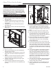
Chateau™ Direct Vent Gas Fireplace Vent Opening for Combustible Wall 16¹⁄₄” (413mm) Firestop Zero Clearance Sleeve Framing Detail 16¹⁄₄” (413mm) X Fireplace Hearth Vent Opening for Noncombustible Wall 11¹⁄₄” (286mm) VO584-100 Fig. 18 Locate vent opening on wall. FP1456 STEP 2 Fig. 20 Vertical height requirement. Measure wall thickness and cut zero clearance sleeve parts to proper length VO584-100 (MAXIMUM 12”/305 mm). AsVent Opening semble sleeve using #8 sheet metal screws (supplied).
Chateau™ Direct Vent Gas Fireplace Support horizontal pipes every 3’ (914 mm) with metal pipe straps. X Check fireplace to make sure it is levelled and properly positioned. Sidewall Installation with Stationary Glass Facing Outside CAUTION: Unit must be installed with stationary glass facing outside. (Control housing will be located on the left side of the unit when facing the unit from inside the house.
Chateau™ Direct Vent Gas Fireplace • The control housing must only be installed on an joints as described on Page 16. Sealing firestop gaps with high temperature sealant will restrict cold air being drawn in around fireplace. STEP 6 Before installing the termination, a 2” (51 mm) thick trim or frame is required around the 16¹⁄₄” x 16¹⁄₄” (413 x 413 mm) square opening to allow the vent termination to go directly onto the elbow. (Fig. 24) 2” (51mm) 16¹⁄₄” x 16¹⁄₄” (413 x 413mm) Opening inside wall.
Chateau™ Direct Vent Gas Fireplace 3. Install the two (2) short brackets, using sheet metal screws, at the top right and left corners of the fireplace window frame. (Fig. 26) NOTE: If top corners of the window frame do not have two (2) pre-drilled holes, you must drill these holes per Step 4. 4. For window frames not having pre-drilled holes: Align the short brackets so the edge of the bracket is exactly aligned with the side edge of the fireplace window’s top flange, as shown in Figure 27.
Chateau™ Direct Vent Gas Fireplace plicable. When using the unitized 30°, 45° or 90° elbows, apply 1/4” bead of high temperature, 550°F or higher, sealant (milpack or stove cement) to the joint of the inner pipe (flue pipe) and the straight section as it is impossible to be taped. The outer pipe must be taped with 315°F high temperature metal adhesive tape for proper sealing. For vertically venting either propane or natural gas units, with vertical vent heights of 12’ (3.
Chateau™ Direct Vent Gas Fireplace This Gas Fireplace has been approved for, • Vertical installations up to 40’ (12 m) in height. Up to a 20’ (6 m) horizontal vent run can be installed within the vent system using a maximum of three (3) 90° elbows. (Fig. 33) • A 2’ (610 mm) vertical section must be installed before any offset. A maximum of 20’ (6.1 m) horizontal and three (3) 90° elbows may be installed with a minimum of 12’ (3.66 m) vertical section above the flue collar of the unit. (Fig. 33) Max.
Chateau™ Direct Vent Gas Fireplace Attic Installation Elbow Strap Nails (4) Support Structure Firestop Spacer Elbow Strap (must be tight) Joist Ceiling Hole Framing Angled Strap Ceiling Installation Angled Firestop Chimney Support Strap (must be tight) Joist FP270/271 FP270/271 Seriesmember. Fig. 37 Attach straps to a structural CR framing 2/19/99 djt Firestop Spacer Nails (4) FP593 Min. 2' (610mm) Fig. 35 Installing firestop spacer.
Chateau™ Direct Vent Gas Fireplace Chimney Components Component Horizontal Starter Kit SK8 Chimney Sections SK8 Chimney Elbows Firestop Zero Clearance Sleeve Attic Insulation Shield Chimney Support Round Top Termination Round Top Termination Extended Flashing Housing Extensions Chase Top Housing Chase Top Housing Horizontal Termination Description Model Number Contains 24”-40” telescopic pipe* for minimum vertical SK8DVSK rise from collar pipe, 90° elbow, horizontal through-wall starter pipe, zero
Chateau™ Direct Vent Gas Fireplace Operating Instructions Glass Cleaning Glass Information Only glass approved by CFM Corporation should be used on this fireplace. • The use of any non-approved replacement glass will void all product warranties. • Care must be taken to avoid breakage of the glass. • Do not operate appliance with glass front • removed, cracked or broken.
Chateau™ Direct Vent Gas Fireplace firebox. Tilt it carefully toward the side until the piece is in place. Using the two (2) brackets and four (4) screws provided with the refractory kit, fasten each bracket to the top of the firebox on each side. NOTE: Use existing holes in firebox. 4. Place the right and left hearth refractories at on each side of the burner tube assembly. 5. Install the end hearth refractories and align with the right and left hearth refractories already installed. 6.
Chateau™ Direct Vent Gas Fireplace Andirons Figure 42 1. Ensure the four (4) screws that attach the fettle to the burner are secure. 2. Set the andirons in place by hooking the tabs on the back of the andirons over the webs of the fettle. (Fig. 42) Repeat process for andirons on both sides of burner. Fettle Burner Housing FP1803 Burner Tubes Figure 43 LG486 Ember Material 3. Place the volcanic rock in front of each burner tube assembly and around the burner assembly as ������ desired. (Fig.
Chateau™ Direct Vent Gas Fireplace 6. Position the log burner overlay. (Fig. 45) The overlay is very fragile and must be handled with extra care. Hold the overlay with the flat surface facing down. The notched corners of the overlay should be on the side of the pilot. Set the overlay on top of the burner housing and align it right to left over the burner housing. Make sure the overlay fits between the two (2) fettles. 7. Position the log grate/burner tube. (Fig.
Chateau™ Direct Vent Gas Fireplace Figure 48 10. Position the log right grate. (Fig. 48) Hold the log with your right hand with the pointed end toward the left and the flat surface facing down. Hook the notch located on the right corner of the log through the first opening on the right hand side of the fettle using the first tine. Bring the log toward you until it comes in contact with the fettle. Then rest the pointed end over the middle log positioned in Step 9. Repeat this step for opposite side.
Chateau™ Direct Vent Gas Fireplace Flame Characteristics It is important to periodically perform a visual check of the pilot and burner flames. Compare them to Figures 51. If the flame patterns appear abnormal contact a qualified service provider for service and adjustment.
Chateau™ Direct Vent Gas Fireplace Trim Installation CAUTION: Allow fireplace to cool if it has been in operation. Trim components: 2 each, top frame assembly, bottom trim assembly, right and left trim assemblies. NOTE: Only one trim set is used when Vista Door is installed. Nailing Flange Trim NOTE: Place trim pieces with magnets facing window frame. 1. Place bottom trim on the bottom of the window frame. NOTE: Final adjustments will be made once all trim pieces are in place. 2.
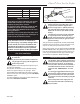
Chateau™ Direct Vent Gas Fireplace Lighting & Operating Instructions For Fireplaces equipped with American Flame Automatic Control System (IN or IP) Warning: If you do not follow these instructions exactly, a fire or explosion may result, causing property damage, personal injury and loss of life. For Your Safety, Read the Following Warnings before Lighting the Appliance A. This fireplace is equipped with an ignition device which automatically lights the pilot and main burner.
Chateau™ Direct Vent Gas Fireplace Troubleshooting American Flame Gas Control System If erratic system behavior is observed that cannot be resolved by the methods outlined below, ensure that there is not a transmitter with batteries installed that may be interfering. If a transmitter is packed with batteries installed, its buttons may be depressed sending a constant signal which can interfere with the transmission of desired signals. A transmitter with new batteries can have a range of over 100’ (30.4 m).
Chateau™ Direct Vent Gas Fireplace Troubleshooting American Flame Gas Control System (continued) Main flame will not light • Verify the gas supply is turned on. • Ensure the pilot flame will ignite. If not, see pilot flame troubleshooting above. • Make sure the green and white leads from the module are securely connected to the terminals labeled “MAIN: on the valve body. • Make certain the pilot flame is in contact with the flame rectification sensor on the pilot assembly.
Chateau™ Direct Vent Gas Fireplace American Flame Gas Control System Error Codes Ignition Safety: Protection for Ignition System Error Code: One beep every one second Description of Fault: Warn users if the pilot is not successfully ignited in 60 seconds. How to Clear: Press OFF then ON buttons to re-attempt ignition. What to Check: • Ensure gas supply is turned on. • Ensure orange/white leads from module are plugged into the “PILOT” connection on the valve body.
Chateau™ Direct Vent Gas Fireplace Fuel Conversion Instructions WARNING! This conversion kit shall be installed by a qualified service agency in accordance with the manufacturer’s instructions and all applicable codes and requirements of the authority having jurisdiction. If the information in these instructions is not followed exactly, a fire, explosion or production of carbon monoxide may result causing property damage, personal injury or loss of life.
Chateau™ Direct Vent Gas Fireplace Index Tab Pilot Adjustment Screw Allen Wrench Snap Ring �� Fig. 56 Remove pilot orifice. 1. Remove two (2) screws holding the pilot assembly to the burner assembly. Move the pilot assembly CO134 toward the back wall. AF pilot orifice 3/07disconnect the gas supply 2. Using a back-up wrench, fitting near the right rear corner of the firebox. 3. Remove four (4) screws holding the burner assembly to the firebox floor. 4. Carefully slide the burner assembly out of the way. 5.
Chateau™ Direct Vent Gas Fireplace 22. Turn on gas supply and operate valve with remote control as needed to indicate gas pressure. The manifold pressure for LP should be approximately 10.0” wcp. CAUTION: Turn off the valve and gas supply before removing test port adaptor and replacing plug. 23. After test, remove adaptor and replace plug. 24. Turn on gas supply and check that plugs are tight and leak free. 25.
Chateau™ Direct Vent Gas Fireplace Maintenance Burner and Burner Compartment It is important to keep the burner and the burner compartment clean. At least once per year the logs and lava rock/ember material should be removed and the burner compartment vacuumed and wiped out. Remove and refit the logs as per the instructions in this manual. Always handle the logs with care as they are fragile and may also be hot if the fireplace has been in use.
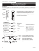
Chateau™ Direct Vent Gas Fireplace 1a 1 1i (2) 3 2 1d (2) 1b (2) 1e 5 1c 7a 6 1j (2) 1f (2) 9a,b 10a,b 11a,b 1h (2) 1g (2) 1k 10a,b 4 4a 8 7b 13 9a,b 4b 14 11a,b 12 11a,b 15 21 16 18 19 17 ON H/L 20 26a OFF/CONTINUOUS PILOT BUTTON 26b 22 26c 26d 26 CFM Corporation reserves the right to make changes in design, materials, specifications, prices and discontinue colors and products at any time, 11957 without notice.
Chateau™ Direct Vent Gas Fireplace DVT38S2 Ref. 1. 1a. 1b. 1c. 1d. 1e. 1f. 1g. 1h. 1i. 1j. 1k. 2. 3. 4. 4a. 4b. 4c. 5. 6. 7a. 7b. 8. 9a. 9b. 10a. 10b. 11a. 11b. 12. 13. 14. 15. 16. 17. 18. 19. 20. 21. 22. 23. 24. 25.
Chateau™ Direct Vent Gas Fireplace DVT38S2 Ref. 26. 26a. 26b. 26c. 26d.
Chateau™ Direct Vent Gas Fireplace Accessories Back-up Battery Kit All Models: DVTBBK Follow instructions provided with the kit and on Page 8 for installation.
Chateau™ Direct Vent Gas Fireplace 46 20011957
Chateau™ Direct Vent Gas Fireplace LIMITED LIFETIME WARRANTY PRODUCT COVERED BY THIS WARRANTY All Vermont Castings brand gas stoves, gas inserts, and gas fireplaces installed in the United States of America or Canada.
Efficiency Ratings Model DVT38S2IN DVT38S2IP EnerGuide Ratings Fireplace Efficiency (%) 47.1 47.1 CFM Corporation 410 Admiral Blvd. • Mississauga, Ontario, Canada L5T 2N6 800-668-5323 • www.cfmcorp.