2ZQHU¶V 0DQXDO
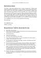
Owner's Manual VERMONA Filter Lancet Introduction The filter is the most essential part of every synthesizer. It allows easy sound manipulation with drastic results. However, why should only synthesizers have all the fun? Drum-computers, groove-machines, guitars and other instruments are equally suited for filtering. This is why external filter boxes like the FILTER Lancet exist! They allow sound manipulation for different kinds of audio signals. In addition, such manipulation should be intuitive.
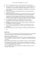
Owner's Manual VERMONA Filter Lancet 11. Only use attachments/accessories specified by the manufacturer. 12. Use only with the cart, stand, tripod, bracket, or table specified by the manufacturer, or sold with the apparatus. When a cart is used, use caution when moving the cart/apparatus combination to avoid injury from tip-over. 13. Unplug this apparatus during lightning storms or when unused for long periods of time. 14. Refer all servicing to qualified service personnel.
Owner's Manual VERMONA Filter Lancet Table of Contents 1 Introduction ..................................................................................................................2 2 Important Safety Instructions ..............................................................................2 3 Table of Contents ......................................................................................................4 4 Getting Started .......................................................................
Owner's Manual VERMONA Filter Lancet Getting Started To ensure top quality we carefully checked FILTER Lancet before packaging. Nevertheless, the unit could have been damaged during transportation. Therefore, we ask you to take a serious look at the unit when unpacking it. Do not hesitate to contact us, should there be anything unusual on MONO Lancet itself or its packaging.
Owner's Manual VERMONA Filter Lancet ATTENTION: Because FILTER Lancet is a filter built of analogue components, it will take 5 to 10 minutes for the parts to reach their appropriate temperature and ensure best tuning stability! Components and Controls Filter Lancet is a filter box. Beside its central sound shaping element, a multimode filter, it offers further functions such as overdrive, VCA, LFO and an envelope-generator.
Owner's Manual VERMONA Filter Lancet ATTENTION: Using too little preamplification will decrease the signal to noise ratio. In addition, trigger sensitivity (see "EnvelopeGenerator (EG)", page 14) as well as the envelope-follower directly depend on the input level setting. Checking for best possible levels is essential for best results of your FILTER Lancet. DRIVE This control adjusts the amount of distortion applied to the input signal.
Owner's Manual VERMONA Filter Lancet BYPASS Setting this switch to BP to disable all sections of FILTER Lancet. The input signal is passed directly to the output after the GAIN stage. With the switch set to ON, all sections are active. Filter (VCF) FILTER Lancet's central sound shaping takes place in its multimode filter section. It can be configured as low pass, high pass and band pass. Each type will suppress certain frequencies that will result in specific sound coloring.
Owner's Manual VERMONA Filter Lancet The filter section offers the following control elements: Picture 3: Filter (VCF) MODE MODE selects the filter type. LP = Low pass Low pass filter with a slope of 24dB per octave BP = Band pass Band pass filter with a slope of 12dB per octave HP = High pass High pass filter with a slope of 24dB per octave BALLS BALLS will emphasize low and higher frequencies in a predefined ratio.
Owner's Manual VERMONA Filter Lancet CUTOFF This control manually sets the filter’s cutoff-frequency. This is the frequency from which the audio signal is manipulated (filtered) with the filter's slope. In low pass mode (MODE LP) the filter is fully opened with CUTOFF turned fully clockwise, closed when turned fully counterclockwise. In high pass mode (MODE HP), the principle of operation works oppositely. When using the filter in bandpass mode (MODE BP), there is no fully opened filter.
Owner's Manual VERMONA Filter Lancet tion while turning left from center results in downward modulation. In its center position, CUTOFF modulation is deactivated. MOD SRC The MOD SRC switch selects the modulation source for the CUTOFF frequency.
Owner's Manual VERMONA Filter Lancet Amplifier (VCA) A voltage-controlled-amplifier (VCA) controls FILTER Lancet’s output. It offers the following control elements: Picture 4: Amplifier (VCA) LFO INT This control sets the LFO's modulation intensity towards the output volume. The result is a tremolo-effect. MODE This switch sets the modulation source for the VCA, respectively sets the VCA to be opened permanently.
Owner's Manual VERMONA Filter Lancet Modulation Modulation-Generator (LFO) The LFO (Low Frequency Oscillator) is an oscillator specialized on slow frequencies that are used to create cyclic repeating modulations. Its frequency is variable, ranging from 0.05Hz to 300Hz, being divided in two switchable ranges. The LFO allows modulating the VCF and/or VCA, each with individually adjustable intensity.
Owner's Manual VERMONA Filter Lancet Envelope-Generator (EG) FILTER Lancet’s envelope generator (EG) generates a variety of envelope shapes depending on the trigger source used. It will work as an Attack/ Decay envelope when using triggers from the audio input or the AUDIO TRIG-input. It will work in three phases (Attack, Sustain, Release) when using the GATE-input. The sustain period cannot be adjust in FILTER Lancet. It is dependent on the duration of the incoming gate signal.
Owner's Manual VERMONA Filter Lancet Envelope Follower (EF) The envelope-follower converts the amplitude characteristic of the audio input signal into a control voltage. Most audio signals do not show clear levels and -jumps as pure control voltages. This results in the envelopefollower being less effective compared to a regular envelope. In most cases, it is therefore necessary to increase the VCF modulation intensity to achieve a comparable effect depth.
Owner's Manual VERMONA Filter Lancet Further Control Elements OVERKILL Connects FILTER Lancet to the AC-power-supply-unit. A green LED shows an active powered unit. ATTENTION: The OVERKILL switch is no power switch. It simply removes the connection to the power supply. Please do always disconnect the PSU from the socket when not using the unit for a longer period! Connectors Find a short description of the connectors on FILTER Lancet’s rear panel: 12 VAC Connect the supplied AC power supply here.
Owner's Manual VERMONA Filter Lancet Technical Specifications Input max. Input Level -32dBu Impedance 1MΩ Output max. Output Level 20dBu Impedance 600Ω Audio Trigger max. Input Level -32dBu Impedance 1MΩ GATE min.
Owner's Manual VERMONA Filter Lancet Switch Range: Lo/Trigger, Lo, Hi Envelope-Generator Attack 1ms..10s Decay/Release 1ms..
Owner's Manual VERMONA Filter Lancet Declaration of Conformity We declare under our sole responsibility that this product is in conformity with the following standards or standardization documents in attention of operation conditions and installation arrangements acc. to operating manual: EN61000-3-2, EN 61000-3-3, EN 55013, EN 55020, EN 60065 according to the provisions of the regulations 2004/108/EG and 2006/95/EG.