
Operation Manual


EN
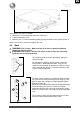
Eclips+ AD
2011-03
!"#$%'&%
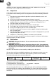
3.9 Adjusting of the pushing handles
!
"WARNING: Risk of injury - Make sure that all screws are properly tightened with
the appropriate tool.
!"WARNING: Risk of tipping over - Make sure that the tubes of the pushing
handles are positioned identically on both sides.
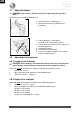
3.9.1 Pushing handles
The tube handle " is fixed to the back frame !.
Adjust the height of the pushing handles as follow:
1. Remove the arm supports.
2. Remove the screws #.
3. Remove the screws $ for suspending the
armrests.
4. Pull the tube handle to the desired height.
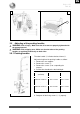
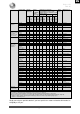
Pusing handle height
Tube handles "
Tube frame !
910 mm (35.83 in.)
(Standard)
Hole 9 and 11
Hole 1 and 2
925 mm (36.42 in.)
Hole 8 and 10
Hole 1 and 2
940 mm (37.00 in.)
Hole 7 and 9
Hole 1 and 2
955 mm (37.60 in.)
Hole 6 and 8
Hole 1 and 2
970 mm (38.19 in.)
Hole 5 and 7
Hole 1 and 2
985 mm (38.78 in.)
Hole 4 and 6
Hole 1 and 2
1000 mm (39.37 in.)
Hole 3 and 5
Hole 1 and 2
1015 mm (39.96 in.)
Hole 2 and 4
Hole 1 and 2
Table 4: Pushing handle heights
5. Retighten all the fixing screws #!$"properly.
1
A
B