
User Manual
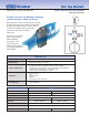

Model Hot Tap • Low Pressure Hand Insertion
V450 Hand Insert/Retract, Low Pressure
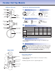
Pipe Size and Schedule or Exact ID and Wall Thickness
Code Sensor Pipe Size Range
10 6” to 42” (150mm to 1050mm)
15 12” to 60” (300mm to 1500mm)
Code Pipe Orientation
H Horizontal
V Vertical
Instrument Connections
(Select Remote or Direct Mount)
(Transmitter sold separately)
Remote Mount Transmitter Direct Mount Transmitter
(1/2” NPT) (Flanged 450°F/232°C Max.)†
Parallel Regular RTD
*
Valve Transmount Mass Transmount
*
Manifold
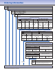
PR D T F G E M
Code Options
SS Wetted Components
WPS
(Furnished with SS weld coupling, flanges & access
nipple). Must be ordered with SS access valve.
Explsn. Proof
Remote
RTD
Integral
RTD
Integral
V450 8”sch40 10 H R C2NC B6CF15 Typical Model Number
Ordering Information
Integral
Mounting Assembly — Select Valve Type, Material & ANSI Class
(Includes valve, WN flange, weld coupling, spiral-wound gaskets, studs & nuts)
Ball Valve Flange
Sensor
(Valve Size)
10 (1-1/2”) 15 (2”) Material & ANSI Class
Code
B6CF15 B8CF15 CS 150#
B6SF15 B8SF15 SS 150#
Gate Valve Flange
Sensor
(Valve Size)
10 (1-1/2”) 15 (2”) Material & ANSI Class
Code
G6CF15 G8CF15 CS 150#
G6SF15 G8SF15 SS 150#
Instrument Valves (Opt.) Manifolds (Optional)
Remote Mount Direct Mount
Needle Gate 3-Valve 5-Valve
C2NC (CS) C2GC (CS) F3SC (CS) F3HC (CS) F5SC (CS) F5HC (CS)
C2NS (SS) C2GS (SS) F3SS (SS) F3HS (SS) F5SS (SS) F5HS (SS)
1/2” NPT Soft Seat Hard Seat Soft Seat Hard Seat1/2” NPT
Optional
*
For high pressure (>500psig) or high temperature (>500°F), remote mount RTD in a thermowell is preferred.
† Assuming adequate heat dissipation for transmitter.