
Install Instructions

Z207062-0A Page 2 of 3 ©2015 Veris Industries USA 800.354.8556 or +1.503.598.4564 / support@veris.com 0115
Alta Labs, Enercept, Enspector, Hawkeye, Trustat, Aerospond, Veris, and the Veris ‘V’ logo are trademarks or registered trademarks of Veris Industries, L.L.C. in the USA and/or other countries.
Other companies’ trademarks are hereby acknowledged to belong to their respective owners.
Installation Guide
Current Monitoring
ECMSeries: HECM
TM
Disconnect and lock out power to the enclosure containing the conductor to be
monitored.
1. Locate a mounting surface for the removable mounting bracket
that will allow the monitored conductor to pass through the center
window when it is installed and that will keep the product at least 1”
(13 mm) from any uninsulated conductors. Determine cable routing
for the controller connection, allowing the wiring to reach the
mounting location.
2. Drill holes to mount the bracket to the chosen surface using the
included screws.
3. Wire the output connections from the sensor to the controller (solid-
state contact).
4. Snap the sensor over the conductor and clip the assembly to the
mounting bracket.
5. Secure the enclosure and reconnect power.
6. Confirm the operation of the sensor with the load running normally.
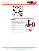
Installation
Dimensions
2.5" *
(64 mm)
2.1"
(54 mm)
3.5"
(89 mm)
2.9"
(74 mm)
0.4” x 0.2”
(10 mm x 5 mm)
Slot (2x)
1.2"
(31 mm)
Removable Mounting Bracket
0.7"
(18 mm)
0.5"
(13 mm)
2.1"
(54 mm)
1.0" *
(26 mm)
0.6"
(16 mm)
Motor (ECM)
Fan
DDC CONTROLLER
DI
Insulated Conductor (line or load) ONL
Y