
Install Instructions

Z207932-0C Page 5 of 12 ©2020 Veris Industries USA 800.354.8556 or +1.503.598.4564 / support@veris.com 0920
Alta Labs, Enercept, Enspector, Hawkeye, Trustat, Aerospond, Veris, and the Veris ‘V’ logo are trademarks or registered trademarks of Veris Industries, L.L.C. in the USA and/or other countries.
Other companies’ trademarks are hereby acknowledged to belong to their respective owners.
CW2 Protocol Series Installation Guide
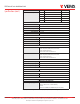
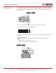
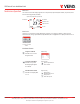
Address the device as any whole number between and including 1 to 127. Note that zero is not a valid address for Modbus;
zero is a valid address for BACnet. Positions 1 through 7 of the “ADDRESS” DIP switch designate the address. Position 8 toggles
between the Modbus and BACnet communication protocols, as shown in the diagram below. This is the left bank of DIP
switches on the sensor.
LS
BM
SB
1 248 16 32 64
Decimal Values
Modbus/BACnet
Toggle
On = Modbus
O = BACnet
Binary Address
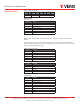
To set an address using the DIP switch, simply add the values of any switches that are in the ON position.
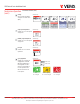
For example, an address of 73 is set as shown in the diagram below.
73
=
LS
BM
SB
1 248 16 32 64
Position number 1 has an ON value of 1, position number 4 has an ON value of 8 and position number 7 has an ON value of 64 (1
+ 8 + 64 = 73).
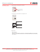
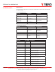
Communications Configuration:
See the Product Diagram section for the location of the DIP switch labeled “CONFIG”. The following parameters are
congurable:
- Parity (Modbus only): None, Odd, None1 (one stop bit), Even
- Baud rate: 9600, 19200, 38400, 57600 (Modbus), 76800 (BACnet)
o o
on o
o on
on on
None
Odd
None1
Even
9600
19200
38400
57600 (Modbus)
76800 (BACnet)
o o
on o
o on
on on
Parity
(Modbus Only) Baud
DIP Switches 5 to 8
are Unused
Installation (cont.)