
User Manual

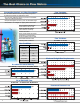

Accelabar Model Selection
1. Furnish your flowing conditions. A flow
calculation is required to determine the
DP and verification of the operating limits.
• Each meter size has a standard beta ratio
sized for the optimal operating range.
• The maximum operating limits are deter-
mined by the Accelabar flow calculation.
2. If your flowing conditions exceed the operating limits, a larger or smaller model (meter size) must be selected.
6
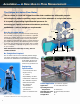
Ready to Install
The Accelabar is a complete flow meter
ready to install. It comes complete with
single or dual transmitters depending on the
turndown requirements.
An optional RTD is supplied in a Thermowell
for dynamic compensation (required for use
with multivariable transmitter).
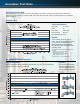
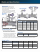
Specifications
Chart A
Meter Size
Verabar
Face to Face “L”*
Sensor
150# 300# 600#
3” (75mm) -05 1/2” 13.78” 14.53” 15.28”
4” (100mm) -05 1/2” 15.15” 15.90” 17.65”
6” (150mm) -10 1” 19.15” 19.90” 21.90”
8” (200mm) -10 1” 21.40” 22.15” 24.40”
10” (250mm) -10 1” 23.15” 24.40” 27.65”
12” (300mm) -10 1” 26.17” 27.78” 29.67”
AF Flanged
Model
Single Transmitter
Dual Transmitter
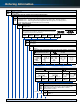
Flowing Conditions
*Density is not required for steam applications.
General Data Fluid Parameters Maximum Normal Minimum Units
Tag number Flow Rate
Pipe size & schedule or
Pressure
exact ID & wall thickness
Temperature
Fluid name: Density*
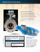
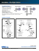
Accuracy Repeatability Sensor, Body & Flange
to ± 0.50% ±0.050% 316SS
Accelabar flow nozzle
Graphite
packing
Packing follower
Weld neck
RF flange
Verabar
Transmitter
RTD
(optional)
Retaining
plate
Manifold
head
L
* Face to face dimensions nominal. Custom lengths available.