Pub.
Pub# OM17-NIR Shank Section 1 MSP with Near Infrared Spectrophotometer Warranty Veris Technologies warrants this product to be free of defects in materials and workmanship for a period of one (1) year from the date of delivery to the purchaser. Veris Technologies will repair or replace any product returned to Salina, Kansas, which appears upon inspection to be defective in materials or workmanship.
Pub# OM17-NIR Shank • Escaping fluid under pressure can penetrate the skin causing serious injury. Avoid the hazard by relieving pressure before disconnecting hydraulic lines. Use a piece of paper or cardboard, NOT BODY PARTS, to check for suspected leaks. • Wear protective gloves and safety glasses or goggles when working with hydraulic and high-pressure wash systems. • If an accident occurs, see a doctor immediately.
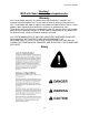
Pub# OM17-NIR Shank Section 2 System Overview Description: The Veris Spectrophotometer acquires absorbance measurements of soil while being pulled through the field. Alternatively, the unit can be set up in stationary mode in a laboratory to acquire absorbance measurements of samples.
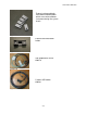
Pub# OM17-NIR Shank Cable that includes fiber, motor control and lamp power Shank module #30267 Figure 4 Garmin GPS # 21221 GPS adaptor cable #30727 Note: This adaptor cable is required in order for compatibility with the provided Garmin GPS. Figure 5 GPS serial adaptor cable #35482 This will connect the serial port of a GPS to the GPS port on the auxiliary case, for using an alternate GPS to the Garmin. External power is required for the GPS to function.
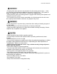
Pub# OM17-NIR Shank External reference blocks and reference block holder which are used to calibrate instrument during the system check.
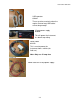
Pub# OM17-NIR Shank USB repeaters #32891 These are to be used only when the regular 5-meter long USB cables are not long enough. Figure 12 15-amp power supply #34669 Figure 13 This will power the instrument in a bench top setting. Power cable #33158 This is used to power the instrument from a vehicle (for field use).
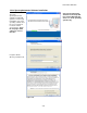
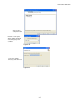
Pub# OM17-NIR Shank Figures 16 & 17 Wearplate assembly #31934 For serial #s 1001 thru 1005 Wearplate assembly #35488 For serial #s 1006 and beyond Note: For computers outside the United States of America, please make the following change to the computer’s regional settings before installing the Veris Spectrophotometer Software. Step 1: Open control panel and double click on Regional and Language Options Step 2: Click on Customize, the following screen will appear. The Decimal symbol needs to be a “.
Pub# OM17-NIR Shank Veris Spectrophotometer Software Installation Veris Spectrophotometer Software V1.77 and up will run on either Windows XP, Vista or 7—32 bit operating systems only The Veris Spectrophotometer Software installer will guide the user through installation of the Veris operating software and the necessary drivers needed to run the spectrometers. Note: Do not plug in USB cables for cases at this time.
Pub# OM17-NIR Shank Select next to complete install Figure 21 Now the ocean optics drivers will be installed. Select language and continue.
Pub# OM17-NIR Shank Next the Hamamatsu Minispectrometer installation guide will appear. Click next two process through the installer Figure 24 At this point it is OK to restart the computer Figure 25 Once the restart is complete, plug in the USB cables for the auxiliary and spectrometer cases MS Windows may then bring up the following screens about the Ocean Optics spectrometer and the Hamamatsu spectrometer.
Pub# OM17-NIR Shank Windows will automatically find the correct drivers for the Ocean Optics USB4000. Figure 27 After completing the Ocean Optics MS Windows installer, the Hamamatsu installer may appear. Note: These installers may appear in any order. For the Hamamatsu installation select Install the software automatically then Next to complete installation. Figure 28 If this screen appears asking for the driver version to be installed always use the specu1a.inf, then select Next.
Pub# OM17-NIR Shank Installation of Calibration Files This must be complete for the software to be operational Copy the master_veris_standards.txt file from the calibration CD into the C:\Veris directory The master_veris_standards file is specific to your external references and is provided by Veris.
Pub# OM17-NIR Shank Configuring Ocean Optics Spectrometer Step 1: Open OOIBase32 Software (only necessary for Veris Spectrophotometer Software V1.76 and below) Start Ocean Optics software (Start programs Ocean Optics OOIBase32) a.
Pub# OM17-NIR Shank If software asks for a default spectrometer file click Cancel Figure 35 Step 2: Open Configuration Click on Spectrometer in the toolbar at the top and then select Configure Figure 36 On the configuration screen select the A/D Interface tab Figure 37 Note: Under Spectrometer Type if USB4000/HR4000 is not available select S4000 2-12
Pub# OM17-NIR Shank Under serial # only one spectrometer number should be present. If no serial number is present close out of the software, unplug the USB cable and reinsert the USB cable, wait to see if windows recognizes a new device, then proceed to the open the Ocean Optics software and try again. Click OK and a spectrum will be present on the screen. Figure 38 Example of spectrum that should be shown on screen (when light is on at shank).
Pub# OM17-NIR Shank Click on Spectrometer then Save Configuration As. Figure 40 The Save Spectrometer Configuration should automatically fill in the file name with the serial number. Click Save. Figure 41 Choose yes to make the spectrometer configuration the default settings. The spectrometer has now been configured. Figure 42 Exit the software.
Pub# OM17-NIR Shank Setting port order - Check Device Manager for port order (Start settings control panel system hardware tab device manager double click ports) - Ports will be listed in order, as they should be set in software. Auxiliary case ports Spectrometer case ports Figure 43 In this example the order to set the ports would be as follows: (see Figure 5.
Pub# OM17-NIR Shank Setting Integration Time: The integration time is the amount of time the spectrometers collect the spectral data for averaging. It is important to have this set correctly because too much light will saturate the spectrometer, while too little light won’t allow the full range of the detector to be used. The integration time needs to be set before acquiring spectral data.
Pub# OM17-NIR Shank Section 3 Field Operations: Electronics Operating software – Software that will guide the user through the field usage steps. This will need to be completed every time the software is started. Open Veris operating software: Folder icon to select working directory. A field folder must be selected before any steps can be completed. Note: Each field or site must have its own folder. BEFORE STARTING: 1.
Pub# OM17-NIR Shank 1) System Check – This step calibrates the spectra data to known standards to ensure data integrity. This is accomplished by A) manually placing four external reference standards against the window and collecting spectra measurements for each standard, then B) transforming the data to a master set of data provided by Veris. A) After the Dark and Reference cycle has completed and the ref check light has turned green, the system is ready for the external references.
Pub# OM17-NIR Shank A yellow ER light indicates possible problem. Regard as a good reference unless transform step fails. Reference check light is green for good references and red for a failed reference. If a reference fails, press F2 to store a new dark and reference. Ref check light Auxiliary data can be scrolled through by the up and down arrows on the left of the indicator. Data corresponds to chart listed on the right of indicator. Note: a reading of –1.
Pub# OM17-NIR Shank B) Transform step. Master data file is provided by Veris. Master data file, which will be used to transform slave (master file provided by Veris) External reference data that was just taken. This compares the slope of the previous transform to the current transform Previous transform will be a straight line the first time system is ran. . Raw master and slave data (external reference). The master is black and the slave is grey.
Pub# OM17-NIR Shank 2) Data Acquisition--electronics – The collection of spectral and auxiliary data in the field. Data is streamed to a file in a compact format. Pressing LOG button or ESC key stores spectrum data as absorbance and auxiliary data, which includes EC data, until LOG button or ESC key has been pressed again. No data can be logged if there is no GPS signal or there is a bad ref check. No data, including EC data, will be stored unless it program is in LOG mode.
Pub# OM17-NIR Shank These indicate the temperatures and the humidity of the system. If they are not within range (see specifications) the indicator light will be red, if this occurs the system should be shut down. Auxiliary data can be scrolled through by pressing the up or down arrow to the left of the indicator. The auxiliary data corresponds to the chart listed on the right of the indicator.
Pub# OM17-NIR Shank How to know you’re collecting high quality NIR measurements: a) Log light and GPS lights are both green b) Ref check light is green c) Spectrum absorbance doesn’t jump as unit is pulled ahead d) Absorbance spectrum shows a typical soil spectra pattern (Figure 52), and is changing slightly as the data is collected. e) External references can be attached to shank at any time in Data Acquisition mode. Absorbance should be highest for ER3 and lowest for ER4.
Pub# OM17-NIR Shank 4) Filtering -The spectra are compressed using principal components compression, and outliers are removed. Maps of each principal component (up to 10) are displayed, and the results of the PC analysis and filtering are output to ASCII formatted files. Score plots of spectrum data that indicate grouping of spectra. Loadings of each principal component. Number of outlying spectra removed during filtering. Total number of spectra. Wavelengths used by the spectrometers.
Pub# OM17-NIR Shank 5) Clustering – Clusters the principal components (PC's) of the spectra into the same number of clusters as desired sample points. When the clustering program opens it will ask if the settings are correct. The settings this refers to are the number of clusters or sample locations, and the number of PC’s to use for clustering. By default there will be 3 PC’s used and 15 locations to sample. If more sample locations are desired, then this can be changed at this time.
Pub# OM17-NIR Shank 6) Soil Sampling – Allows the user to navigate to the GPS coordinates of desired sample locations (from Step 5), and record actual sample locations. The actual locations that are saved during sampling program will be used for the interpolation of the spectra in the next step. Map of the proposed locations (black circles) and the actual locations (black squares).
Pub# OM17-NIR Shank 7) Interpolation – Uses a Gaussian weighting to average spectra near a sampled location. Spectra near to the location are weighted higher than spectra far away. Outputs a file named spectra@locations.txt to the working directory. This file contains the spectra and auxiliary data for each sampled GPS location. Once the interpolation begins it will ask if the settings are correct. The settings this refers to are a, b, and the depth increments.
Pub# OM17-NIR Shank How to import sample locations for interpolation with Veris software (versions 1.4 and later) This is only to be used when sampling is not completed in the Veris software. By following these steps the user could map a field and then flag the GPS locations where samples were collected and use those locations to get the interpolated values from the Veris software. Step 1: Collect field data, then extract and filter the data.
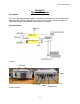
Pub# OM17-NIR Shank Bench top Usage To use the spectrophotometer to obtain measurements in the a bench top setting, first complete the system check as described in the field usage steps, then proceed to the acquisition. Mount the shank against the shank bench top stand (shown below). Place a soil sample in the sample holder and place the holder against the face of the shank window. Use the sample button or F4 to store a dark, reference, and then a sample spectrum.
Pub# OM17-NIR Shank Placing the sample holder securely against the shank.
Pub# OM17-NIR Shank Test/Example Data In order to gain experience with the software before mapping, test/example datasets are included with the Veris software. This allows the user to experiment with the system, without logging data or having GPS signal. 1. Start Operating software ( Start programs Veris Spectrophotometer Software Veris Data Processing) 2. Select working directory by clicking on folder icon. Figure 18 3. Set ports (see setting port order) 4.
Pub# OM17-NIR Shank Field Operations—NIRS and Soil EC Mobile Sensor Platform Checking Electrical Signal Continuity and Electrode Isolation It is recommended that you routinely check the EC signal to verify that all functions are working properly. See Maintenance and Lubrication Section for a step-by-step procedure. It is advisable to perform this test on a routine basis (weekly or every 20-25 hours of data collection) to ensure you are obtaining reliable data.
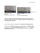
Pub# OM17-NIR Shank Swath width and Navigation Setting the swath width and navigation system is at the discretion of the customer. A 40-60’ (12-18 m) swath works well in most areas. In areas of high soil variability, a narrower swath may be preferred. Several methods of navigation are possible: following previous crop rows, swath guidance, or using a field navigation computer.
Pub# OM17-NIR Shank set screws and jam nuts Figure 23 Coulter: Pull MSP forward and check depth of coulter and shank. Coulter should be cutting residue ahead of shank, but not penetrating deeper than the shank. Adjust height of coulter by loosening top and side jam nuts and set bolts, and re-positioning coulter. Do not remove top bolt or coulter may drop out of holder.
Pub# OM17-NIR Shank Optical shoe leveling: once the mainframe is level, and you have chosen the desired operational depth, the final adjustment is the forward and backward tilt of the optical shoe. 1) Lower into the soil and pull forward with the shank in the soil. 2) Check to see of the trailing edge of the shoe is firmly down on the surface of the soil. 3) If not loosen both ½” mounting bolts and rotate cam to allow forward or rear adjustment, re-tighten and run again.
Pub# OM17-NIR Shank • Pinch point hazard: to prevent injury, stand clear when raising or lowering any part of the Veris MSP. Disengage automatic cycling function before working around unit. • Install all transport locks before transporting or working underneath. Closing disks: Adjust closing disks as needed to properly close trench and bring residue over row-cleaned zone. Do not operate these deeper in soil than necessary.
Pub# OM17-NIR Shank Section 4 Maintenance and Lubrication Proper maintenance and lubrication of the Veris MSP will allow you to collect high quality NIRS and EC data, and greatly extend the useful life of the unit. Veris Technologies strongly suggests that you follow the following guidelines: MAINTENANCE: Storage of Spectrophotometer Spectrometer and Auxiliary cases are water resistant; store NIRS system indoors or under roof.
Pub# OM17-NIR Shank Connect one lead to Test Box terminal (corresponding to each coulter) Ohmmeter Connect to coulter blade Figure 3 c) Continue to check each coulter electrode in succession, left to right. d) If any coulter electrode exhibits no continuity or resistance higher than 2 ohms, refer to the maintenance or trouble shooting sections for possible causes.
Pub# OM17-NIR Shank 3 27 LOG Figure 5 Note: It is advisable to conduct this test as a routine check to ensure that you are obtaining reliable EC data. ADJUSTMENTS Commutators-The spring-loaded commutators are located in the center of each coulter electrode hub cap. They are factory preset, and should not need routine adjustment. If a continuity test shows abnormally high resistance, the commutators should be checked. This may be performed in the following manner: 1) Remove the 3/8” allen head set screw.
Pub# OM17-NIR Shank Here is a cut away view of the hubcap assembly: Setscrew cap commutator spindle Figure 6 Note: If you are still unable to obtain favorable resistance readings, check for excessive corrosion at the coulter blade mounting bolts, or the terminal located near the coulter pivot. It may be necessary to grind the spindle end smooth, if a dimple has developed. MAINTENANCE: LUBRICATION • Pinch point hazard: to prevent injury, stand clear when raising or lowering any part of the Veris MSP.
Pub# OM17-NIR Shank Pivot grease zerks (2 per hangar; 4 total ) Figure 7 Rachet jack -- 20 hour intervals grease zerks Figure 8 Electrode coulters Pivot --In all but the most extremely rocky conditions, the coulter electrodes should not flex in the field, thus minimal movement will be realized at the pivot. 80-hour intervals should be sufficient. grease zerk Figure 9 Hubs --Use good quality wheel bearing or lithium grease for lubrication, but we suggest that you grease the hubs sparingly.
Pub# OM17-NIR Shank seal failure, and an excessive amount of grease in the hub cap/commutator. On an interval of 150 hours, 1-2 strokes of grease should be sufficient. grease zerk Figure 10 Wheel hubs -On an annual basis, disassemble, clean, and properly repack the wheel hubs with suitable wheel bearing grease. It is advisable to replace the seals. As with any tapered roller bearing, proper pre-load will extend the life of the assembly.
Pub# OM17-NIR Shank 7) Adjust bearing pre-load as mentioned above. Excessive preload may cause plugging in extremely loose soil conditions, and excessive endplay may damage the commutators. 8) Inspect the sealing o-ring on the hub cap, and reinstall by threading counter-clockwise on the hub. 9) Adjust commutator clearance as mentioned above in section on commutator adjustments.
Pub# OM17-NIR Shank Maintenance: NIRS Wear-plate Replacement • Pinch point hazard: to prevent injury, stand clear when raising or lowering any part of the Veris MSP. Disengage automatic cycling function before working around unit. • Install all transport locks before transporting or working underneath. Step 1: Pull shank back and secure with pin in the top hole of the black adjustment bar.
Pub# OM17-NIR Shank Step 4: Using 3/16 hex wrench remove the four bolts securing shank wear plate. 3/16 hex bolts Figure 14 Step 5: Insert new O-ring into new shank wear plate.
Pub# OM17-NIR Shank Step 6: Make sure both the surface of the wear plate and the surface of the shank are clean before placing the new shank wear plate onto shank and securing with four new bolts.
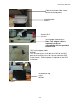
Pub# OM17-NIR Shank Shank Removal This procedure is needed when removing the shank for bench top use or for repair. Shank bulkhead connector box Bulkhead connector box screws. Note: There are four screws total. Only two are pictured here, the other two are on the opposite side. Fiber optic cables Note: Always place caps on fiber connector after disconnecting, to prevent fiber from getting contaminated.
Pub# OM17-NIR Shank Shank side plate bolts Figure 19 Shank bolts Temperature module bolts Step 4: Remove the four shank side plate bolts on the left side using a 3/8” socket wrench. Remove the shank side plate and set aside. Step 5: Remove the two temperature module bolts on the left side using a 3/8” socket wrench. Step 6: Remove the two shank bolts on the left side using a 3/8” socket wrench.
Pub# OM17-NIR Shank Temperature module bolts Figure 20 Shank bolts Step 4: Remove the two temperature bolts on the right side using a 3/8” socket wrench. The temperature module should be free now. Remove and place to the side. Step 5: Remove the two shank bolts on the right side, the shank should now be free.
Pub# OM17-NIR Shank Case Removal and Installation When the spectrometer and auxiliary cases need to be removed for storage, repair, or bench top use follow these instructions. First disconnect all wires and the optical fibers connected to the auxiliary and spectrometer cases. Each case is secured with two latches, and case and latch assembly can be removed as a unit.
Pub# OM17-NIR Shank Section 5 Troubleshooting Troubleshooting EC module Map doesn’t match known or expected soil types -1. Check electrical continuity using Implement Test Box as discussed above. 2. Check isolation of coulter electrodes 3. Remove any buildup of moist soil on toolbar 4. Check blade bolt tightness and corrosion 5. Map additional fields to see if similar condition results 6.
Pub# OM17-NIR Shank Troubleshooting NIRS No spectrum is present on graph or spectrum is not updating in Acquisition 1. Ensure USB cables are tightly connected 2. Shut down software and cases and restart system 3. Check port settings 4. Open each spectrometer individually in the manufactures software(procedure #7 & 8) MS Windows brings up an new hardware found wizard when I plug in my cases 1.
Pub# OM17-NIR Shank Troubleshooting NIRS continued Auxiliary data not updating or ports not setting up correctly 1. Shut down power, and restart cases 2. Ensure USB cables are secured tightly 3. Follow the steps outlined in procedure #10, to ensure data is present on the ports. How many times do I need to run system check? A system check transform should be run at least once for each field mapped. Is the data treated before output to file? The data is not pretreated before output.
Pub# OM17-NIR Shank Problem: No response from Hamamatsu Spectrometer (1100-2200nm) Does Hamamatsu software open? (Proc. #7) NO Error stating cannot find/open device Does Hamamatsu report error message? YES Hamamatsu is operating correctly. Restart Veris Spectrophotometer Software and try again. Error stating temperature out of range Check the device manager for Hamamatsu hardware. To do so Right click on the My Computer icon on the desktop.
Pub# OM17-NIR Shank Troubleshooting GPS If GPS fails to come in it could be for a variety of reasons. The easiest way to isolate the problem is to open the GPS port in HyperTerminal (see troubleshooting with HyperTerminal). GPS port open in HyperTerminal Is data streaming in HyperTerminal ? (Proc.
Pub# OM17-NIR Shank Procedure #1 Check Ocean Optics spectrometer This procedure is only necessary with Veris Spectrophotometer Software V1.76 and below 1) Click on start Programs Ocean Optics OOIBase32 Start OOIBase32 software 2) Check graph it see if spectrum is present (see figure below). The spectrum should change as different objects are placed in front of the window on the shank. Figure 1 3) If there is no spectrum present or graph does not update as objects are placed beneath the shank.
Pub# OM17-NIR Shank Figure 2 4) Under Spectrometer Type select S4000. For the A/D Converter Type select USB4000. The USB Serial Number will have one serial number present, which is unique to each spectrometer, select the available serial number. 5) Click OK to save the settings and return to the main screen. A spectrum should now be present. 6) Close OOIBase32 software, restart computer, and open Veris Spectrophotometer Software to begin mapping again.
Pub# OM17-NIR Shank Procedure #2 Check Hamamatsu spectrometer 1) Click on Start Programs HamamatsuMinispectrometer EvaluationSoftware SpecEvaluation 2) Click on open spectrometer Figure 3 Open spectrometer icon 3) Click on Open under Select Spectrometer Figure 4 4) Click on start and check to see if spectrum graph changes as different objects are placed under shank window. This ensures the Hamamatsu spectrometer is working properly.
Pub# OM17-NIR Shank Start Figure 5 5-9
Pub# OM17-NIR Shank Procedure #3 - Shutter Movement Troubleshooting During data acquisition if the steps are not within 5.21 +\- .05, or if there are problems doing dark/reference checks, the shutter could either be out of sequence or not operating properly. Complete the steps below to get the shank back into sequence. N= neutral, window open, light visible, no actuator rod Shutter is shown in neutral position. Note light has been turned off for photograph.
Pub# OM17-NIR Shank Step 4: Type ”S” (data should start streaming); EN etc This number is the steps of the shutter. In this example it is 1025 Figure 9 Step 5: Type “R” and wait 10 seconds; ER etc should appear. Step 6: Type “D” and wait 10 seconds; ED etc should appear. Step 7: Type “N” and wait 10 seconds; EN etc should appear.
Pub# OM17-NIR Shank Procedure 4 - Troubleshooting NIRS with HyperTerminal If auxiliary data fails to come in properly, then the port and device can be verified outside of the software by utilizing the HyperTerminal. If the port works properly here then the data should be present in the Veris Operating software.
Pub# OM17-NIR Shank o Enter com port properties for your device. See the Port Properties section for the standard settings. Figure 12 o Click OK o HyperTerminal session now open and data should be present. See Port Definitions for example HyperTerminal data. .
Pub# OM17-NIR Shank o Control Port Bits per second: 9600 Data bits: 8 Parity: None Stop bits: 1 Flow control: None o Spectrometer Port Bits per second: 9600 Data bits: 8 Parity: None Stop bits: 1 Flow control: none Port Definitions o Temperature Port – Reads in soil temperature. Example of temperature port connected in HyperTerminal o GPS Port – Reads in GPS coordinates. Example of GPS port connected in HyperTerminal.
Pub# OM17-NIR Shank Example of Control Port in shank mode connected in HyperTerminal. How to read control port data strings Shank Mode E shutter position, current, voltage deep, voltage shallow * T temperature, humidity, shutter steps, 0, 0* o Spectrometer Port – Reads in Spectrometer temperature and humidity, side box temperature, cooler state, and spectrometer cooler state.
Pub# OM17-NIR Shank Procedure #5 - Fuse replacement There are two fuses inside the spectrometer case and one inside the auxiliary case. To locate and replace these fuses, follow these steps. First remove the cases see procedure #6 Spectrometer case fuses The first fuse is on the side control box. This is a four-amp fuse, which protects the power to the Hamamatsu spectrometer as well as the internal microcontroller.
Pub# OM17-NIR Shank Ocean Optics USB4000 spectrometer Edgeport hub Silica gel packet used to remove moisture in the air. Note: If humidity in spectrometer case is above 90% this packet needs to be replaced. Figure 15 Inside view of spectrometer case mounting shelf To reach the fuse for the Edgeport first disconnect the fiber optic cable to the USB4000, then disconnect the USB output cable.
Pub# OM17-NIR Shank Edgeport hub power board, also the temperature and humidity readings are monitored from this board Figure 18 Spectrometer case mounting shelf tilted back. Fuse can be removed using screwdriver. Replace only with 3-amp fuse.
Pub# OM17-NIR Shank The fuse for the auxiliary case protects the voltage for the electrical conductivity board and the lamp. To replace the fuse open the case and locate the black fuse holder Fuse holder. Replace only with a 4-amp fuse.
Pub# OM17-NIR Shank Procedure #6 - Checking Spectrometer Input Voltage and Hamamatsu Voltage Connect the positive lead from the voltmeter here (white wire) Figure 21 Connect negative lead from voltmeter here (brown wire) 5-20 Voltage should read 5V, as long as spectrometer case is within temperature range.
Pub# OM17-NIR Shank Procedure #7 Replacing halogen lamp 1. Remove the shank from the implement following procedure on page 4-11 2. Remove the top plate on the shank by unscrewing four screws Figure 22 USE CAUTION WHEN HANDLING TOP COVER! TOO MUCH MOVEMENT CAN FLEX AND BREAK THE FIBER OPTIC CABLE. 3. Using a 3/32 hex wrench loosen the set screw holding in the lamp housing.
Pub# OM17-NIR Shank 4. Now remove the housing, use a 3/32 hex wrench to loosen the set screw holding in the lamp. Figure 24 5. Disconnect the lamp and replace with a new lamp Figure 25 Handle the lamp with care. Make sure not to touch the bulb itself. The bulb can fair prematurely if oils are on the bulb. Bulb can be cleaned with alcohol if touched. 6. Reassemble the shank following the same steps used for disassembly.
Pub# OM17-NIR Shank Glossary Spectrophotometer – A complete system for making spectral measurements. The system includes a light source, means for collecting light that has interacted with the material under test, and a spectrometer to measure the collected light. Spectrometer – Instrument to measure the quantity of light over a spectrum of wavelengths. The spectrometer is the "measurement engine" of the spectrophotometer.
Pub# OM17-NIR Shank Field Auxiliary output definitions EC_Sh – Electrical conductivity shallow. EC_Dp - Electrical conductivity deep.
Pub# OM17-NIR Shank xform_*.txt Transform created by comparing master_veris_standards and latest xternal_reference files. raw_spectra_*.bytestream Field data taken in compact bytestream format. Note: Each time system check is ran a new .bytestream file and xform.txt file will be created. Once system check has been completed successfully, then the .bytestream file will automatically be appended to if acquisition is stopped and started again later. field spectra.
Pub# OM17-NIR Shank The P_Sample, P_Long, P_Lat, P_Depth are the actual sample number, longitude, latitude, and depth. The # Spec refers to the number of spectra found near each sample location. These are the locations that were selected in the sampling program. The depth is only used in the probe mode. The next 17 columns are the interpolated data found near each of those actual locations. Then the next 384 columns are the interpolated spectra data found near each of the actual locations.
Pub# OM17-NIR Shank Program Modifications The files in the C:\Veris directory are used to store configuration settings for the Veris Operating software. These are set to default values, but can be changed. Veris directory files Description acq_settings.txt Stores acquisition settings, these can be configured by the user. Ex. 0.010 19.000 5.000 15.000 0.150 0.150 0.300 0.150 2.
Pub# OM17-NIR Shank Spectra depth column (probe mode only) ports.txt Stores ports and baud rates from previous time system was run. ref_wavelengths.txt Stores values of the useable wavelengths for each spectrometer, which can be configured by the user. These wavelengths will be used to filter the data. Ex. 450.000 950.000 1150.000 2150.