OM17-Quad1000 Operating Instructions Quad 1000 Soil EC Mapping System Table of Contents Section 1 1-2 1-3 Warranty Safety Section 2 2-1 2-3 2-4 Electronics Overview and Set-up: EC Surveyor Electronics Overview and Set-up: DataLogger Software Set-up: SoilViewer Section 3 3-1 3-2 Implement Overview and Set-up Additional Assembly Instructions Section 4 4-1 4-2 4-4 4-5 Field Operations—EC Surveyor Field Operations—EC Surveyor with DataLogger Field Operations—EC Surveyor with SoilViewer software Field O
OM17-Quad1000 Quad 1000 Soil EC Mapping System Soil EC Surveyor Software Version 1.2 Sensor DataLogger Version 1.03 Section 1 Warranty Veris Technologies warrants this product to be free of defects in materials and workmanship for a period of one (1) year from the date of delivery to the purchaser. Veris Technologies will repair or replace any product returned to Salina, Kansas, which appears upon inspection to be defective in materials or workmanship.
OM17-Quad1000 Important! Read the following SAFETY PROCEDURES before operating the Veris system: • Read and understand all instructions on safety decals • Properly block up implements befor working underneath. • Detach and store implements in an area where children normally do not play. Secure implement by using blocks and supports.
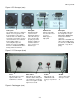
OM17-Quad1000 EC Surveyor SD card reader Serial cable Signal test box SoilViewer software Mtg bracket Signal test load Mtg bracket Power cord Power cord Figure 1. EC Surveyor kit Figure 2. DataLogger kit Use protective shipping/storage case to protect electronics components whenever electronics are shipped. Keep all diagnostics and operations manual with system when mapping. Mount instrument in a location that is as free as possible from dust, vibration, and electrical interference.
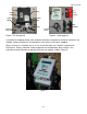
OM17-Quad1000 Figure 4. EC Surveyor (rear) Power port: The Soil EC Surveyor is shipped with an accessory power cord. If an alternative connection is desired, make sure that the unit is properly connected to a power connection that is not controlled by the ignition switch. If connecting directly to the battery, we suggest a 3-amp inline fuse is installed between the battery and the instrument. EC Signal: EC Signal Cable extension from implement attaches to the EC Surveyor here.
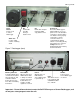
OM17-Quad1000 Reset button: Can be used to reboot DataLogger EC: Serial cable from EC Surveyor attaches here. pH: Serial cable from pH Controller (MSP only) attaches here. Alarm Vol: Used to adjust volume of auditory alarm Figure 7. DataLogger (front) Memory Card slot: Formatted SD memory card must be installed when booting up, and at all times data is being collected. See Proc. #6 for formatting instructions. Data Status: When lit, this green LED indicates data is being recorded to memory card.
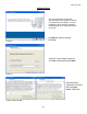
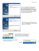
OM17-Quad1000 Software Setup The Veris SoilViewer software will automatically run the setup once the CD is inserted into the computer. If not the installation can be manually started by double clicking on the setup.exe located on the CD. Click Next to continue through installation Figure 8. Once the CD has begun select the installation directory and click Next Figure 9. Next two license agreements will need to be accepted before continuing. Figures 10a and 10b.
OM17-Quad1000 The installer will install all necessary components Figure 11.
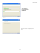
OM17-Quad1000 The Veris SoilViewer will now install drivers necessary to operate the included USBSerial Converter (part #41377). If you do not want to use the included converter than press cancel here, otherwise click next. If you have the USB- Serial converter plugged in be sure to unplug it before clicking next. Figure 13 After the drivers are successfully installed click finish and Restart your computer before opening Veris SoilViewer.
OM17-Quad1000 Section 3 Implement Overview and Set-up Weights Raise/lower crank Signal Cable quickconnect coupler port Disk electrodes Tongue Tire and Wheel Assembly Implement hitch Figure 1. The tongue must be installed prior to use. To do so, please take precautions to ensure that the framework is properly supported to ensure safety. 1) Remove bands that attach tongue and framework to shipping pallet. 2) Install tongue as shown in Figure 2. Install tongue with ½” X 3.
OM17-Quad1000 NOTE: Depending on shipping configuration, the unit may need additional assembly. Attach wheels as shown in Figure 3. Attach raise-lower crank bracket as shown in Figure 4. Attach wheels with ½” X 2.75” bolts with lock washer and nut. Figure 3 Install raise-lower crank bracket with ½” X 3.75” bolts with lock washer and nut. Figure 4 Attach raise/lower crank to disk electrode toolbar by threading crank rod into trunion as shown in Figure 5.
OM17-Quad1000 Install weight bracket if included as shown in Figure 7. A choice of assembly positions is available to accommodate customer-provided suitcase weights. Properly installed weights will provide positive tongue weight, but still allow user to lift tongue without straining. If tongue weight is excessive, move bracket to middle or rear holes; if tongue weight is negative (tongue won’t stay down) move weight bracket forward.
OM17-Quad1000 Section 4 Field Operations—Soil EC Surveyor Attach the signal cable to the quick connect coupler at front of frame, and to Signal port on back of EC Surveyor. Connect serial cable, GPS, and power cords to ports on rear of EC Surveyor. Figures 1a and 1b EC Surveyor display readings Here are the display readings that you will see when operating the EC Surveyor: Figure 2 The unit is ready to operate.
OM17-Quad1000 Field Operations—Soil EC Surveyor with Sensor DataLogger Before logging any data, make sure the SD card in the Datalogger is clear of any files that are not Veris .dat files. Any other files will cause the data an error when logging data. The Veris DataLogger is not compatible with SDHC cards. Only SD cards will work correctly.
OM17-Quad1000 If memory card was not inserted during boot-up, the following screen will appear: Figure 8 Install card and re-start DataLogger. NEVER REMOVE CARD WHILE LOGGING DATA. This is the Data Acquisition screen: Shallow (S) and Deep (D) soil EC readings. If negative, no data will be recorded. (on Quad 1000 ignore Deep reading) Figure 9 GPS status: may read GPS, DGPS, RTK, or None. If None, no GPS signal is received and no data will be recorded.
OM17-Quad1000 Field Operations—Soil EC Surveyor with SoilViewer software The EC Mapping software will automatically detect which port the Veris EC Surveyor is connected to, and begin communicating. If the EC Surveyor is not detected, the software will wait 45 seconds for the connection of the Surveyor and search again; this is repeated until the Surveyor is connected. If the Surveyor is not found, unplug the serial or USB cable and reconnect it to the PC.
OM17-Quad1000 Field Operations--Implement Checking Electrical Signal Continuity and Electrode Isolation It is recommended that you perform the Electrical Signal Continuity and Electrode Isolation test procedure before first field use (see Maintenance and Service Procedures 1 and 2). While these tests were made at the factory, there is the possibility a problem developed during shipping.
OM17-Quad1000 Swath width and Navigation Setting the swath width and navigation system is at the discretion of the customer. A 50’-75’ (1523 m) swath works well in most areas. Several methods of navigation are possible: following previous crop rows, swath guidance, or using a field navigation computer. While it is important to map in a consistent pattern, it isn’t absolutely critical that each pass be exactly the same distance from the previous pass.
OM17-Quad1000 Section 5 Troubleshooting EC data seem odd—jumpy, negatives, map doesn’t match known or expected soil types Perform Maintenance and Service Procedures 1-3. No GPS or DGPS on display Perform Maintenance and Service Procedure 5 DataLogger locks up -SD card not installed or not formatted. See Procedure #6 to format card.
OM17-Quad1000 SoilViewer Troubleshooting EC Surveyor is not found Check to ensure the com which the EC Surveyor is connected to is present under the device manager. To get to the device manager go to StartSettingsControl PanelSystem Click on the Hardware tab and then click on the device manager button. Click on the “+” sign next to Ports and make sure the port is listed here.
OM17-Quad1000 Reinstalling USB- Serial Converter (Part# 41377) Drivers Insert the Veris SoilViewer disk once the Veris SoilViewer appears click cancel. Open My computer and right click on the CD rom drive then click on Explore Figure 2 Double Click on PL-2303 Driver Installer.exe follow the installation guide to install the driver, then restart your computer and plug in the USB- Serial converter cable to try again.
OM17-Quad1000 Section 6 Maintenance and Service Procedure #1: EC Surveyor Instrument Signal Testing Perform this test daily or every 10 hours of data collection to ensure you are obtaining reliable data, and whenever EC data is questionable. The purpose of this test is to insure that the instrument is performing properly. The EC Surveyor is shipped with an Instrument Test Load (Part No. 10447) that will enable you to quickly check the instrument to ensure that it is functioning properly.
OM17-Quad1000 Procedure #2: Testing Electrical Continuity Perform this test daily or every 10 hours of data collection to ensure you are obtaining reliable data, and whenever EC data is questionable. The purpose of this test is to insure that each disk-electrode has an uninterrupted signal path from the EC Surveyor to the disk blade. Think of each disk-electrode and its wire path as a ‘channel’. On a Quad1000, there are 4 signal channels that must be clear and isolated from each other.
OM17-Quad1000 Signal extension cable (from implement) Figure 2.2 Firmly press one lead of the ohmmeter to the #1 disk blade edge (left hand, standing behind the unit) and the other lead to the terminal marked #1on the Quad 1000 test box decal. Maintain firm pressure on the ohmmeter lead touching the disk blade. A reading of less than 2 ohms is normal. Rotate blade ¼ of a turn back and forth as you view the ohmmeter. Any jump in the readings above 2 ohms indicates a problem. (Figure 2.
Procedure #3: Diagnosing and Correcting EC Signal Problems. OM17-Quad1000 Use this Troubleshooting tree to work through the system, locate the problem, and take corrective action. Figure 3.
OM17-Quad1000 Disk Electrode FunctionsEach disk electrode on the implement is part of a pair, and each pair has a distinct function. a) Disks 1 & 4 are the “charged” disks that inject the voltage into the soil. b) Disks 2 & 3 are the “Shallow EC” receptors. If the continuity ohm test indicates a problem on a channel, you will need to determine where the interruption is located. Listed below are detailed instructions on how to determine exactly where a continuity or isolation problem is located: A.
OM17-Quad1000 Coulter 2 Coulter 3 Coulter 1 Coulter 4 Figure 3.3. Check continuity of signal harness, with one ohmmeter lead contacting pin in connector and other lead contacting corresponding disk-electrode. If that test shows < ohms of resistance, test signal extension cable as shown in Figure 3.4 Coulter 1 Coulter 3 Coulter 2 Coulter 4 Figure 3.4.
OM17-Quad1000 Figure 3.5 2. If ohms jump over 2 ohms when the blade is rotated, and you were careful to maintain good contact between the lead and the blade, the problem is likely inside the hub. Because electrical signals cannot be sent consistently through the disk bearing, Veris has designed a more reliable path for the EC signal to travel. A special hub with a spring plunger presses against the bolt through the bearing, serving as a commutator. Shown below in Figure 3.
OM17-Quad1000 C. Testing Disk-Electrode isolation If continuity tests show no excessive resistance on any channel, yet erratic soil EC readings continue, or if EC readings do not drop to –1 when unit is out of the soil, it is possible that the channels are not isolated. This could be the result of a pinched wiring cable, causing channels to short out. Or, one of the disk-electrodes is no longer insulated properly from the frame or adjacent disk-electrodes. 1.
OM17-Quad1000 grounded bolt disk wire connector bolt no continuity Figures 3.10 a and b 4. Wet soil on the toolbar could be a pathway for the EC signal to short. Test disk-to-disk and disk-to-frame isolation by checking resistance between disk-electrodes. Any continuity from one disk to another is not acceptable. Remove buildup of wet soil, especially if is bridges across insulation slides. It may be necessary to remove disk mounting brackets and clean toolbar, if problem persists.
OM17-Quad1000 Procedure #4 Spring Plunger adjustment and replacement The spring plungers are located in the center of each disk electrode hub cap, and are vital to maintain good continuity through the disk hub bearings. They are factory preset, and should not need routine adjustment. If a continuity test shows abnormally high resistance, the plungers should be checked. This may be performed in the following manner: 1) Check disk hub bearing preload by grasping disk blade and pushing from side to side.
OM17-Quad1000 Procedure: 1) Remove hub cap by removing the four carriage bolts. 2) If plunger is frozen in cap, remove the 3/8” nut on the outside of the hub cap and apply penetrating oil on both sides of plunger. Let this stand for a few minutes and try to remove. If it will not back out with allen wrench, lock vise grips on the inside portion and turn out through inside of hub. 3) Clean all hub cap surfaces, coat plunger with di-electric grease and install as outlined above.
OM17-Quad1000 Procedure #5: Diagnosing GPS-related problems If you do not see a GPS, DGPS, or RTK in the upper left-hand corner of the EC Surveyor screen, you do not have GPS coming in, and no data will be sent out the serial port for logging. Figure 5.1 Insure your GPS receiver is powered and outputting NMEA strings GGA, and either VTG or RMC at a 1hz rate; 4800 baud, 8 data bits, no parity, 1 stop bit.
OM17-Quad1000 If it becomes necessary to send GPS data into your PC, you will use a program called HyperTerminal. This program is in all Windows software. It is designed to record serial data streaming into a serial or USB port on the computer. The purpose of this is two-fold: 1) it verifies whether your GPS and cables are delivering the proper messages, and 2) it give Veris Technologies support personnel a GPS data file to test. Here’s how to use HyperTerminal 1.
OM17-Quad1000 5. The program will then ask you for a phone number. Instead of entering a phone number, specify the proper serial port number. For example, if Com 1 of the laptop is being used, specify “Direct to Com 1” under “connect using:” at the bottom of the entry area. Figure 5.5. 6. HyperTerminal will then display a configuration menu where you can specify 4800 bits per second, 8 data bits, no parity, 1 stop bit and no flow control. Figure 5.
OM17-Quad1000 7. At this point, upon clicking ok, legible strings of GPS data should begin appearing on the laptop screen. Here’s an example of a typical set of strings: $GPGGA,191528.00,3851.0333,N,09737.2342,W,2,08,1.3,372.7,M,27.3,M,10.0,0100*69 $GPRMC,191528.00,A,3851.0333,N,09737.2342,W,0.1,0.0,090998,6.3,E*48 8. If GPS data doesn’t appear, recheck the port and configuration settings to make sure they are correct.
OM17-Quad1000 Procedure #6: SD card formatting and firmware updates USING A VERIS SD CARD IN OTHER DEVICES CAN CAUSE FILE CORRUPTION. Insert a standard SD card (not SDHC type) into a SD card reader which connected to your computer. Open “My Computer” folder. Right click on the SD card icon, and select the “Format”. Figures 6.1 a and b. In the format window, click on the file system tab and select “FAT” not “FAT32”. Then press “Start”. When complete, remove the card. Updating Data Logger Firmware 1.
OM17-Quad1000 Figure 6.2. 6. Hold the (1) key and release the RESET button. 7. If you can see the following messages, then release the (1) key. Figure 6.3 8. If you want to update new software, press (2) key.
OM17-Quad1000 9. Then you can see the following messages in sequence. Figures 6.4 a and b. 10. Do not shut off the power, but repeat from step 5 to 9 again. 11. Press the RESET button or shut off and turn back on the power. 12. Check the LCD display. If nothing shows up in the LCD, or if display doesn’t contain the new firmware version number, please repeat from step 1 to 11.
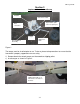
OM17-Quad1000 Procedures #7: Lubrication and #8: Maintenance Raise/lower crank: this should be lubricated on 20-hour intervals. This may vary based on the number of times the unit is raised and lowered. Figure 7.1 Disk and bearing: Bearings are sealed and do not require any maintenance. Under normal use, the blade and bearing are an assembly and have approximately the same life. Under rare circumstances, it may be necessary to replace them separately.
OM17-Quad1000 Procedure #9: Removing EC Surveyor Cover: Microchip Replacement and Q1000 to 3150 Resistor Change It may be necessary to open the EC Surveyor to perform one of the service functions listed below. Disconnect power cable. Remove four screws in front end plate, and pull end plate slightly to free up top panel. Be careful not to pull too hard and disconnect any wires. Figures 9.2 a and b. Slide top panel out to reveal circuits. Figure 9.
OM17-Quad1000 Replacing microchip. If microchip fails, or if unit needs updated firmware, it will be necessary to remove chip and replace with new one. Before chip removal and installation, touch grounded metal to discharge your static electricity. Remove chip with pliers or chip puller. Install new chip, making sure that notch in plastic housing is to the right. Be careful to not damage pins of new chip as it is installed Figure 9.4 notch notch Figure 9.5 a and b.
OM17-Quad1000 Figures 9.5 a, b, c 9a: Resistor installed for Q1000, 2000XA and 3100 models; 9b and c: position for 3150 models: resistor in storage position—not being used; 9c resistor removed Resistor can be removed or installed by hand as shown below. Figure 9.