Pub.# OM17-PRC Operating Instruction Manual Precision Rate Controller Veris Technologies 601 N. Broadway Salina KS 67401 (785) 825-1978 www.veristech.
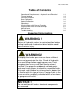
Pub.# OM17-PRC Table of Contents Operational Requirements—Hydraulic and Electrical Tractor Hookup Console Functions Rate Calibration Speed Calibration Operations Varying Rates with Pre-set Function Varying Rates with GPS-based maps Maintenance Troubleshooting Important Information WARNING ! Return all hydraulic valves to neutral position before exiting tractor cab. Inadvertent drive rotation could cause serious injury.
Operating Instructions Drive Operational Requirements: Hydraulic System: Closed center, pressure compensated or load sensed systems only Drive will not operate on open-centered hydraulic systems Minimum Hyd. Pressure: 2250 psi Maximum Hyd. Pressure: 3000 psi Maximum Required Flow: 8.
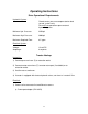
Pub.# OM17-PRC Connect to power port Connect to console Connect to power wire from implement Figure 1 b) To battery. Make sure that eyelets are properly connected (red to positive, Black to negative). Connect female socket to power port adapter.
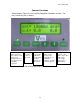
Pub.# OM17-PRC Console Functions Shown below in Figure 3 is the Precision Population Controller Console. The uses of each key are as follows: On/VR key—turns drive system on. Press twice for VR mode. Note: Engage key must also be pressed to start drive operation. Off key: used to shut off Console. Function key: used in calibration mode and to program Console for VR recipes. Up/down arrow keys: used to change rates manually, to set calibration numbers, and VR controller options. Figure 3.
Pub.# OM17-PRC Calibration--Rate Turn on Controller Console by pressing On/VR key. Green light above On/VR key will illuminate when power is on. Adjust desired planting rate by using the Up/Down arrow keys to change the Set rate. (See Figure 4) Figure 4. Set the desired Rate by using the Up/Down arrow keys. Press Function key until Calibration Number window appears. (See Figure 5) Select drive calibration number from chart if available. If calibration number is not known, enter 1000.
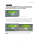
Pub.# OM17-PRC Figure 7. This is the first window that appears in Calibration mode. Press Function key to accept, or Up key to change to metric settings. Figure 8. Enter implement width here using Up/Down arrow keys. Press Function key to advance to next window. Figure 9. Enter number of rows here using Up/Down arrow keys. Press Function key to advance to next window. Figure 10. Enter your planned planting speed using Up/Down arrow keys. Calibration mode will not accept a speed higher than 10 mph.
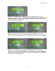
Pub.# OM17-PRC Figure 12. The cab console is informing you the length of time that the drive will be operating, in order to meter the amount of seed you have requested, at the calibration number, planter or application width, and number of rows you have selected. If the screen reads TIME TOO LOW, you will need to increase the amount of seed that you will count or measure. Press Function key to advance to next window. Figure 13.
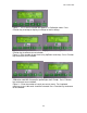
Pub.# OM17-PRC Figure 16. While the drive is rotating, the display window shows the time remaining and the “Out” rate. CONTINUE TO MONITOR DRIVE AREA DURING DRIVE ROTATION. PRESS THE ENGAGE KEY (OR OFF KEY) TO STOP DRIVE DURING CALIBRATION Figure 17. After Calibration meter rotation has ended, the screen above left will appear. Enter the actual amount metered using the Up/Down arrow keys as shown in Figure 18, above right. Press Function key to advance to next window. Figure 19.
Pub.# OM17-PRC Figure 21. Console window now displays the calibration number you have selected. This returns you back to the beginning of Calibration mode as shown in Figure 5. To re-run the Calibration procedure, follow the steps outlined above. It is suggested that you perform the calibration mode at least twice, and additional replications may be needed if Target and Actual amounts vary significantly.
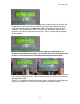
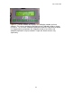
Pub.# OM17-PRC Calibration—Speed In order for the Precision Rate Controller to meter the proper amount of material, it must have an accurate field speed input. Speed may be supplied by radar or by wheel pickup sensor. For the Controller to convert the pulses that it is receiving from the speed input into accurate speed, it must be calibrated. To calibrate the Controller for speed, press the Function key until the screen appears, as shown in Figure 22: Figure 22. Speed calibration screen Figure 23.
Pub.# OM17-PRC Figure 24 and 25. When the tractor passes the second flag, press engage again. (Figure 26) The display will show the error or difference between the traveled distance and the distance calculated by the Controller. (Figure 27) Figures 26 and 27. If this is the first time the unit has been calibrated, this error can be large. Accept the new speed calibration and re-run the course. Re-calibrate until the error is within 5%.
Pub.# OM17-PRC Field Operations 1. Once calibration procedure above has been followed, Console will store the calibration and rate information until new information has been entered. 2. Turn on Controller Console by pressing the On/VR key. Green light above On/VR key will illuminate when power is on. Pressing the On/VR key twice will put the unit in VR mode. (See Figure 29) VR will appear on the screen along with the Rate that is being sent from the computer.
Pub.# OM17-PRC 5. Press Engage key to activate drive. Green light above Engage key will illuminate. After 20 seconds of no speed signal, drive will disengage. This is to help prevent inadvertent entanglement in planter drive mechanism. To restart drive after it has disengaged, press Engage key. 6. The Console display shows two numbers while operating: “Set” rate is the rate you tell the system to plant, and the “Out” rate is the calculated rate based on the actual rotations of the drive.
Pub.# OM17-PRC Varying Rates with Pre-set Function The Veris Precision Rate Controller allows you to pre-set three different rates, and then change rates on-the-go by toggling from one rate to another rates with the Up or Down arrow keys. To enter the three pre-set rates, press Function key until Pre-set Menu screen appears: (Figure 30) Use Up-Down arrow keys to toggle from manual mode to pre-set mode.
Pub.# OM17-PRC Varying Rates with GPS-Based Maps Settings for FarmWorks SiteMate used with Veris Precision Rate Controllers— QUICK REFERENCE GUIDE (Create a .shp recipe file in FarmWorks Site Pro, SMS 2.0, SSToolbox, or other software that will create a .shp file, and transfer it to SiteMate.) SiteMate Settings: (version 8.12) 1. Select CONFIGURE Tab. Select SETTINGS. Select VARIABLE RATE SETUP. Select NEW. Type in GP PPC. Under CONTROLLER TYPE, select Rawson from the scroll-down list.
Pub.# OM17-PRC Settings for Veris Precision Rate Controllers: 1. Connect SiteMate computer to Cab Console using 9-pin serial cable, as shown in Figure 23. 2. Set Calibration Number as described on pages 6-10 3. Press Function key and go to Rawson mode. Press Function key until the Nominal Rate appears on the display. Using the Up/Down arrow keys, set the Nominal Rate to the same number as you entered in the SiteMate program in step 4 above.
Pub.# OM17-PRC Population Monitor rate does not match Veris Console. -Make certain that SiteMate and Console agree. If not, see Troubleshooting step 4 above. -Re-check GP calibration number, with metering wheel and row spacing. -Re-check planter monitor settings: calibration number, row spacing, number of rows, swath width, seed, etc.
Pub.# OM17-PRC PF3000 Settings: 1. Press SETUP key. Press SWATH key. Set swath to that of your implement 2. Press SETUP key. Press VEHICLE key. Set Primary speed sensor to GPS. 3. Press SETUP key. Press CARD key. Set the following: Log Device: None. 4. Press SETUP key. Press APP RATE key. Set the following: Application Control: On Look Ahead: On Current target file: press Edit to view the files you have on the card; select the one you wish to use. 5. Press SETUP key. Press CONTROLLER key.
Pub.# OM17-PRC Settings for Veris Precision Rate Controllers: 1. Connect PF3000 to Console using 9 pin serial cable as shown in Figure 33. 2. Set Calibration Number as described on pages 6-10. 3. Press Function key and go to Rawson mode. Press Function key until the Nominal Rate appears on the display. Using the Up/Down arrow keys, set the Nominal Rate to the same number as you set the PF3000 in step 5 above.
Pub.# OM17-PRC 10. Population Monitor rate does not match Veris Console. -Make certain that PF3000 and Veris Console agree. If not, see Troubleshooting step 3 above. -Re-check calibration number, and re-run calibration procedure if necessary -Re-check planter monitor settings: calibration number, row spacing, number of rows, swath width, seed, etc.
Pub.# OM17-PRC Maintenance As with any hydraulic system, contamination is the most common cause of performance problems and pre-mature wear. Make a special effort to properly clean quick couplers prior to attaching the hoses to tractor. 1) Filter --All fluid is filtered through the high pressure filter (PN 18574) and it will provide protection to the hydraulic components of your drive if properly maintained.
Pub.# OM17-PRC Troubleshooting Drive will not rotate: (see Troubleshooting flow chart and electronics overview) 1. Check cab console: 1.1) No power to cab console – check with voltmeter. 1.2) Upper line (set) is visible but no lower line (out rate and speed) on display: move to Communication troubleshooting below 1.3) 1 or 10 amp fuse on power cable may be blown. d) Engage button is not on – check to see if green indicator light is on. 1.
Pub.# OM17-PRC 4. Check hydraulics: 4.1) Check to see if hydraulic lever is in detent position. 4.2) Hydraulic lever is in wrong detent direction--a check valve at outlet of motor prevents reverse rotation. 4.3) Make sure that both hoses are properly connected to tractor remotes. 4.4) Inadequate system pressure. Place pressure gauge at filter and check reading. If system Rapid drive rotation pressure is below tractor specifications, check may occur and system. 4.
Pub.# OM17-PRC Drive rotates but not at desired speed: 6. Drive (out rate) fluctuating erratically 6.1) If indicated field speed on drive is also fluctuating erratically, trouble-shoot speed signal loop 6.2) If field speed is steady, check for loose set screws on motor encoder, contamination of proportional valve, or mechanical binding of chain on row unit 7. Indicated speed fluctuating erratically. 7.1) Use speed simulator to troubleshoot speed loop.
Pub.# OM17-PRC 10. Drive plants significantly higher than desired rate: 10.1) Re-check calibration number, and re-run calibration procedure if necessary 10.2) Ensure that you have installed the correct seed meter. 10.3) Check sprocket combinations; see Assembly and Parts Manuals for the planter you are operating (30P and 40P models) 10.4) Check speed shown on cab console against other speedometer—tractor, planter monitor. If drive speed is significantly higher, recalibrate speed on drive. 11.
Pub.# OM17-PRC Calibration Troubleshooting: 13. If the time to run for calibration is less than 4 seconds, the cab console will display TIME TOO LOW. Pressing the FUNCTION key will bring up the ENTER TARGET AMOUNT screen. The target should be raised to increase the calibration time. If the time is greater than 255 seconds, the cab console will display TIME TOO HIGH. Pressing the FUNCTION key will bring up the ENTER TARGET AMOUNT screen. The target should be lowered to decrease the calibration time. 14.