OM17-P4000 Force/EC Operating Instructions EC Force Probe Table of Contents Section 1 1-1 Warranty & Safety Section 2 2-1 2-3 System Overview P4000 System Overview Electronics Section 3 3-1 Software Installation Guide Section 4 4-1 Field Operations – Electronics Section 5 5-1 5-3 5-4 5-6 5-8 5-10 Probe Platform Installation Platform Operation EC - Force Probe Operation Soil Coring Soil Anchoring System Probe Removal and Tractor Installation Section 6 6-1 6-4 6-5 Maintenance and Lubrication Probe
OM17-P4000 Force/EC Warranty Veris Technologies warrants this product to be free of defects in materials and workmanship for a period of one (1) year from the date of delivery to the purchaser. Veris Technologies will repair or replace any product returned to Salina, Kansas, which appears upon inspection to be defective in materials or workmanship.
OM17-P4000 Force/EC Important! Read the following SAFETY PROCEDURES before operating the Veris P4000 • Escaping fluid under pressure can penetrate the skin causing serious injury. Avoid the hazard by relieving pressure before disconnecting hydraulic lines. Use a piece of • Use paper or cardboard, NOT BODY PARTS, to check for suspected leaks. • Wear protective gloves and safety glasses or goggles when working with hydraulic and high-pressure wash systems. • If an accident occurs, see a doctor immediately.
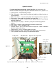
OM17-P4000 Force/EC Section 2 VERIS P4000 Probe Platform System Overview Before you begin using your P4000, it’s important to familiarize yourself with the basic components and controls Pre-operation checks: 1) Engine oil Level – refer to Honda GX 670 engine manual 2) Hydraulic fluid -- fluid level should be at or near upper black line on sight gauge of hydraulic reservoir. (Figure 1). If not add suitable ISO 32 hydraulic fluid with a viscosity index of 95- 140.
OM17-P4000 Force/EC Hydraulic Controls All system monitoring and probe control functions are contained on the console mounted to the right of the probe, referred to as the “foot”. (Figures 3,4) a) Voltage meter – monitors battery voltage b) Side shift control – allows lateral movement of probe for multiple insertions at a given location.
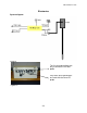
OM17-P4000 Force/EC Electronics System diagram Figure 5 The first four connections are only used with the VIS NIR probe Only these three connections are used with the Force EC probe Figures 6 2-3
OM17-P4000 Force/EC Cable that includes force and EC connections Probe module #38145 Figure 7&8 Garmin GPS # 21221 GPS adaptor cable #30727 Note: This adaptor cable is required in order for compatibility with the provided Garmin GPS. Figure 9 GPS serial adaptor cable #35482 This will connect the serial port of a GPS to the GPS port on the auxiliary case, for using an alternate GPS to the Garmin. External power is required for the GPS to function.
OM17-P4000 Force/EC 5-meter USB cable #30281 Figure 12 Power cable #39985 This is used to power the instrument from a vehicle (for field use).
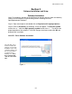
OM17-P4000 Force/EC Section 3 Software Installation and Setup Software Installation Note: For computers outside the United States of America, please make the following change to the computer’s regional settings before installing the Veris Spectrophotometer Software. Step 1: Open control panel and double click on Regional and Language Options Step 2: Click on Customize, the following screen will appear. The Decimal symbol needs to be a “.” while the Digit grouping symbol needs to be a “,”.
OM17-P4000 Force/EC Only install software in the default directory. If a different directory is chosen then the auxiliary case will not be able to find the correct drivers.
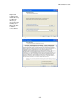
OM17-P4000 Force/EC Click next to install software Figure 4 Figure 5 Click finish to exit installer Figure 6 3-3
OM17-P4000 Force/EC Section 4 Field Operation - Electronics The Force EC probe software will acquire a EC and force measurement for every 2cm the probe is inserted. Before opening software turn on power to the auxilary case and connect via USB cable to the PC. To begin data acquisition open the software and select a file to be saved.
OM17-P4000 Force/EC Place the probe tip at the desired starting point, check to ensure the GPS signal light is green and press log or hit Enter and begin to insert the probe to store data. The log light will turn green indicating the software is in log mode. Data is collected and averaged every 2cm. Once the 2cm interval is reached the data light will flash and the data is written to the output file. Once the desired depth is reached pull the probe out and Log will be shut off.
OM17-P4000 Force/EC Section 5 Field Operation P4000-S Installation The P4000-S is designed to be installed in ¾ ton – 1 ton pickups and due to the wide range of bed and frame dimensions on the market, there are no mounting holes in lower frame flange. Some drilling and fabrication will be required. You may choose to perform this on your own, or may wish to have a local welding or truck shop do this for you.
OM17-P4000 Force/EC Top View Figure 2A & B Start out with ¼” pilot hole for drilling up through bed, then enlarge to ½” or larger from on top 5) Using the “L” straps as templates, you can drill the hole through the bottom side of the skid frame rail. Tip: If you start out with small pilot holes (1/4”or less) it takes less effort to drill through the bed and frame rail, then drill out to full dimension from on top.
OM17-P4000 Force/EC Field Operation Probe Platform - Start engine and allow to warm a minute or two before cycling – a few minutes if during cold weather. Extend to full rear position Fold into upright position (figure 5) Lower foot to soil Raise probe (figure 6) Install Probe or core sampling components Figure 5 Figure 6 KEEP FEET CLEAR OF FOOT AND PROBE Important! -- When folding and retracting the platform make sure that probe mast clears engine muffler.
OM17-P4000 Force/EC Field Operation EC - Force Probe Checking Electrical Signal Continuity and Electrode Isolation It is recommended that you routinely check the EC signal to verify that all functions are working properly. See Maintenance and Lubrication Section for a step-by-step procedure. It is advisable to perform this test on a routine basis (weekly or every 20-25 hours of data collection) to ensure you are obtaining reliable data. Operation Begin field operation by lowering the foot to the soil.
OM17-P4000 Force/EC Figure 9 Speed Probe speed is not recommended over 30mm/sec, for optimal data resolution. This is adjustable via the probe speed flow control on the side of the control panel. (Figure 9 above) A maximum probe speed of 50mm/sec should not be exceeded or else data could be missing from the output file. Field Condition Field should be in a uniform state. Probe after intensive primary tillage is not recommended. The soil must have a minimum of 10% available water, and cannot be frozen.
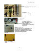
OM17-P4000 Force/EC Field Operations Soil Coring Once you have competed probing, remove EC - Force probe as outlined in Section 6. - Install drive coupler to rotating head by means of drive retainer (Figure 10) - Install PETG liner onto cutting shoe and thread into sampling tube (Figure 11) - Install sampling tube into drive coupler and push into soil. Figure 10 Figure 11 Use slow and steady insertion speed and minimal rotation to push core sampler into the soil.
OM17-P4000 Force/EC Remove sampler tube and remove cutting shoe from sampling tube by tapping and rotating, or by use of wrench (provided). (Figure 13) Cap the lower end of core with black vinyl cap, and the top with red.
OM17-P4000 Force/EC Field Operations Optional Anchoring System In some field conditions it may be necessary to drive soil anchors into the soil to obtain adequate depth with probe or core sampler. If this is the case, you will need PN 40209 Anchoring Package. Installation and Removal - - Retract probe until is in the most forward position. Side shift to the far right and lower foot. Place anchor in center of foot opening and lower probe drive until hex enters hex drive on probe.
OM17-P4000 Force/EC 1. Extend platform out to full extension 2. Attached chain binders on each side of probe 3. Slip anchor plates over anchors and bind down each side (figure 18) Figure 18 - Anchoring will limit your side travel somewhat, but you should still be able to take multiple cores with the anchors installed. Do not use extension control while anchors are connected Remove the anchors in reverse sequence.
OM17-P4000 Force/EC Field Operations P4000T Removal and Tractor installation The P4000 is designed to work equally well on a tractor, or as a skid mount unit. Removing probe from skid – - Install three point stabilizer stands into probe and temporarily lock in mid position with ¾” pinch bolt. Extend and unfold the probe. Lower foot to ground level. Remove fold cylinder pin, and carefully retract fold cylinder until it is fully retracted.
OM17-P4000 Force/EC Figure 21 Fold and Extend hoses Disconnect wiring Installing on Tractor – - All bushings and pins are provided for Category I and II three-point hitches. Connect lower links – make sure you include the stabilizer link bushings(Figure 24) Connect top link Raise three point to desired height and level with top link Install lower stabilizer mount on drawbar and tighten 5/8” bolts Connect LH and RH stabilizer to upper and lower points, adjust, and lock with jam nut.
OM17-P4000 Force/EC Section 6 Maintenance and Lubrication Proper maintenance and lubrication of the Veris P4000G will allow you to collect high quality EC and force, and greatly extend the useful life of the unit. Veris Technologies strongly suggests that you follow the following guidelines: MAINTENANCE: Storage of Auxiliary Instrument and EC – Force Probe The auxiliary instrument and probe are water resistant; store system indoors or under roof.
OM17-P4000 Force/EC Instrument EC Signal Testing – The Veris Auxiliary Instrument is shipped with an Instrument Test Load (Part No. 10447) that will enable you to quickly check the instrument to ensure that the EC circuit is functioning properly. To perform this test, do the following: 1) Disconnect the signal cable from the amp pin (signal) terminal on the auxiliary case. 2) Connect the test load to the signal terminal. 3) Turn on Auxiliary Instrument and start up software.
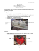
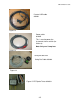
OM17-P4000 Force/EC Probe EC Signal Testing – The EC – Force probe is shipped with a EC dipole tester (Part No. 29689) that will enable you to quickly check the probe and instrument to ensure the EC is functioning correctly. To perform this test, do the following: 1) Press one bolt of the dipole tester to the side of the probe tip and the other to the center brass dipole. (see figure 5 below) Depending on if the brass or the silver bolts are used the EC reading will be high or low.
OM17-P4000 Force/EC Probe Removal This procedure is needed when removing the probe for bench top use, road transport, or for soil coring. Step 1: Disconnect the force, EC, USB, and power cables to the auxiliary case. Loom Clip Step 2: Remove loom from clip. Step 3: Mounting Pin Cables Figure 6 Step 3: Firmly grasp probe, and remove the mounting pin holding the probe on the platform.
OM17-P4000 Force/EC Case Removal and Installation When the auxiliary case needs to be removed for storage, repair, or bench top use follow these instructions. First disconnect all wires connected to the auxiliary case. The case is secured with two latches, and case and latch assembly can be removed as a unit.
OM17-P4000 Force/EC Section 7 Troubleshooting Troubleshooting EC module Data missing from display reading – 1. Unit must be in contact with soil to record data points 2. Check GPS and DGPS signal; Veris instrument is programmed to eliminate all nonDGPS geo-referenced points. 3. Shut power off and restart 4. Check electrical continuity 5. Check input voltage, 12 v minimum required No GPS data is coming in during acquisition 1. Check to ensure nothing is obstructing GPS signal (ex. buildings) 2.
OM17-P4000 Force/EC Troubleshooting GPS If GPS fails to come in it could be for a variety of reasons. If using the provided Garmin GPS make sure the GPS adaptor is in place (see figure 10 in system overview). Then following troubleshooting tree to isolate the problem.
OM17-P4000 Force/EC Fuse Replacement The fuse for the auxiliary case protects the voltage for the electrical conductivity board and the lamp. To replace the fuse open the case and locate the black fuse holder Fuse holder. Replace only with a 4-amp fuse.
OM17-P4000 Force/EC Section 8 Specifications Max ambient temperature to operate system: 110 degrees F Max aux case temperature: 65 degrees C Max aux case humidity: 90% RH Max force sensor capacity: 22361 kPa or 3245 PSI Max probe insertion speed: 50mm/s WARNING: Damage to force sensor may occur if this specification is exceeded 8-1