
Mapping System - Trouble-shooting Manual
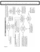
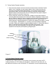

Coulter Electrode Functions-
Each coulter electrode on the implement is part of a pair, and each pair has a distinct
function.
a) Coulters 1 & 6 are the Deep EC receptors. If you are seeing problems only with the
―Deep‖ readings, focus on testing continuity on these two coulter-electrodes.
b) Coulters 2 & 5 are the ―charged‖ coulters that inject the voltage into the soil. If you
are getting no (or intermittent) readings on both the ―Shallow‖ and the ―Deep‖ --
continuity to one of these two coulter-electrodes is likely the cause.
c) Coulters 3 & 4 are the ―Shallow EC‖ receptors. Focus on this pair if you see
problems in the ―Shallow‖ reading.
If the continuity ohm test indicates a problem on a channel, you will need to determine
where the interruption is located. Listed below are detailed instructions on how to
determine exactly where a continuity or isolation problem is located:
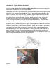
A. Testing Cable and Wiring continuity:
1. Once a high resistance reading on a channel is confirmed, determine whether the
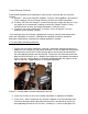
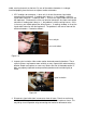
problem is in the wiring or in the coulter-electrode. To test all cable and wiring, place
one ohmmeter lead in the Test Box terminal pin for that channel and the other on
the corresponding coulter wire terminal bolt. Grasp sure-seal connector and move
back and forth during this test – vibration from rough fields can weaken the contacts
on the sure seal, causing breaks in continuity during operation that might no show
up in a static test. Repeat process on all coulter-electrodes.
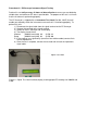
Figure 3.2 Testing cable at coulter electrode #3 terminal
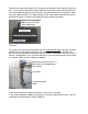
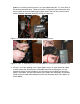
2. If you see <2 ohms on all, test the coulter electrodes as explained in B below.
3. If you see a > 2ohms reading on any channel, separate sure-seal connector and
insert one ohmmeter lead in the end of wiring harness and the other lead in the
corresponding terminal on the Test Box. If reading is < 2 ohms at that point, the