Pub.
Pub. # OM17-EC VERIS 2000XA, 3100, 3150 Soil EC Mapping System Soil EC Surveyor Software Version 1.2 Sensor DataLogger Version 1.03 Section 1 Warranty Veris Technologies warrants this product to be free of defects in materials and workmanship for a period of one (1) year from the date of delivery to the purchaser. Veris Technologies will repair or replace any product returned to Salina, Kansas, which appears upon inspection to be defective in materials or workmanship.
Pub. # OM17-EC Important! Read the following SAFETY PROCEDURES before operating the Veris system: • Read and understand all instructions on safety decals • Escaping fluid under pressure can penetrate the skin causing serious injury. Avoid the hazard by relieving pressure before disconnecting hydraulic lines. Use a piece of paper or card-board, NOT BODY PARTS, to check for suspected leaks. • Wear protective gloves and safety glasses or goggles when working with hydraulic and highpressure wash systems.
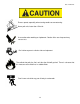
Pub. # OM17-EC Excess speed, especially when turning could cause overturning. Never pull units faster than 15 km/hr. Use caution when working on implement. Coulter disks are sharp and may causes cuts. Don’t allow anyone to climb or ride on implement The vehicle that pulls the Veris unit thru the field will get hot! There is a chance that this heat can cause field fires in stubble fields.
Pub. # OM17-EC Keep safety chain installed Install jack before unhitching; do not drop unit on foot FCC NOTE This equipment has been tested and found to comply with the limits for a Class A digital device, pursuant to Part 15 of the FCC Rules. These limits are designed to provide reasonable protection against harmful interference when the equipment is operated in a commercial environment.
Pub. # OM17-EC EUROPEAN DECLARATION OF CONFORMITY Veris Technologies, Inc., located at 601 N. Broadway in Salina Kansas, certifies that the product: Veris 2000XA is in conformity with the following directive and standards: Machinery Directive 2006/42/EC--1st Edition—December 2009 Electromagnetic Compatibility 2004/108/EC —December 2004 EN55022 – Measuring Radiated Emissions The Technical File is maintained at: Veris Technologies, Inc. 601 N.
Pub. # OM17-EC EUROPEAN DECLARATION OF CONFORMITY Veris Technologies, Inc., located at 601 N. Broadway in Salina Kansas, certifies that the product: Veris 3150 is in conformity with the following directive and standards: Machinery Directive 2006/42/EC--1st Edition—December 2009 Electromagnetic Compatibility 2004/108/EC —December 2004 EN55022 – Measuring Radiated Emissions The Technical File is maintained at: Veris Technologies, Inc. 601 N.
Pub. # OM17-EC Statement of Use Intended use of the Veris 2000XA The Veris 2000XA Soil EC Mapping System collects geo-referenced soil electrical conductivity (EC) measurements as it is pulled across a field by a tractor or an ATV/Quad bike. An electronic device called the Soil EC Surveyor, powered by vehicle’s 12V DC electrical system, generates a small electrical current, which is transferred into the soil through a pair of rolling electrode coulter disks.
Pub. # OM17-EC Statement of Use Intended use of the Veris 3150 The Veris 3150 Soil EC Mapping System collects geo-referenced soil electrical conductivity (EC) measurements as it is pulled across a field by a tractor or an pickup truck. An electronic device called the Soil EC Surveyor, powered by vehicle’s 12V DC electrical system, generates a small electrical current, which is transferred into the soil through a pair of rolling electrode coulter disks.
Pub. # OM17-EC 2000XA Lifting Points Below are the recommended lifting points for the unit. Using two straps you can safely lift the unit. Make sure the straps used to lift are rated greater than 1200 lbs. Fork extensions maybe required to lift. Always stay clear when lifting the unit.
Pub.
Pub. # OM17-EC 3150 Lifting Points Below are the recommended lifting points for the unit. Using two straps you can safely lift the unit. Make sure the straps used to lift are rated greater than 1200 lbs. Fork extensions maybe required to lift. Always stay clear when lifting the unit.
Pub. # OM17-EC Section 2 Electronics Overview and Set-up The Veris Electronics kits includes the following items: Protective case DataLogger EC Surveyor SD card reader Serial cable Signal test box SoilViewer software Mtg bracket Signal test load Mtg bracket Power cord Power cord Figure 1. EC Surveyor kit Figure 2. DataLogger kit Use protective shipping/storage case to protect electronics components whenever electronics are shipped.
Pub. # OM17-EC Figure 4. EC Surveyor (rear) Power port: The Soil EC Surveyor is shipped with an accessory power cord. If an alternative connection is desired, make sure that the unit is properly connected to a power connection that is not controlled by the ignition switch. If connecting directly to the battery, we suggest a 3-amp inline fuse is installed between the battery and the instrument. EC Signal: EC Signal Cable extension from implement attaches to the EC Surveyor here.
Pub. # OM17-EC Reset button: Can be used to reboot DataLogger EC: Serial cable from EC Surveyor attaches here. pH: Serial cable from pH Controller (MSP only) attaches here. Alarm Vol: Used to adjust volume of auditory alarm Power port: The Sensor DataLogger is shipped with an accessory power cord. If an alternative connection is desired, make sure that the unit is properly connected to a power connection that is not controlled by the ignition switch.
Pub. # OM17-EC Important – Do not allow moisture to enter the Soil EC Surveyor or Sensor DataLogger, and do not pass strong magnets near the unit. Software Setup The Veris SoilViewer software will automatically run the setup once the CD is inserted into the computer. If not the installation can be manually started by double clicking on the setup.exe located on the CD. Click Next to continue through installation Figure 8. Once the CD has begun select the installation directory and click Next Figure 9.
Pub. # OM17-EC Next two license agreements will need to be accepted before continuing. Figures 10a and 10b. The installer will install all necessary components Figure 11.
Pub. # OM17-EC The Veris SoilViewer will now install drivers necessary to operate the included USBSerial Converter (part #41377). If you do not want to use the included converter than press cancel here, otherwise click next. If you have the USB- Serial converter plugged in be sure to unplug it before clicking next. After the drivers are successfully installed click finish and Restart your computer before opening Veris SoilViewer.
Pub. # OM17-EC Section 3 Implement Overview and Set-up (3100 shown) Ratchet for raising/lowering Jack location for field operation Weights Road kit: stop, turn, and clearance lights Signal Cable quickconnect coupler port 4-bolt hubs and P205 R75 highway tires Jack location for implement storage Implement hitch (2” ball) Coulter electrodes Rockshaft and frame Tongue Figure 1. If the unit is crated, the tongue must be installed prior to use.
Pub. # OM17-EC 3. Install tongue with two 5/8’ X 41/2” bolts and torque to 170 ft lbs Figure 3. Electro-hydraulic Lift Kit Set-up The Electro-hydraulic Kit is shipped in a pre-assembled state, and has been tested prior to shipment. Figure 4. Hyd Power Unit Remote Control Figure 5.
Pub. # OM17-EC Installation: 1) Locate power unit in desired location in towing vehicle. If the unit is to be used on a dedicated unit, we advise anchoring it securely to prevent tipping or damage in rough field conditions. Mounting holes are located on each side of base. 2) Connect ground (black) power cable to negative post on towing vehicle battery. 3) Connect power (red) cable directly to the positive post on the battery. Quick connect to power unit.
Pub. # OM17-EC Bleeding Pressure from System If the hoses have been disconnected while under pressure, if one hose disconnects during operation, or if the remote is depressed while not connected to cylinder, you will likely build pressure in the system and will not be able to reconnect the hoses. • Escaping fluid under pressure can penetrate the skin causing serious injury. Avoid the hazard by relieving pressure before disconnecting hydraulic lines.
Pub. # OM17-EC Section 4 Field Operations—Soil EC Surveyor Attach the signal cable to the quick connect coupler at front of frame, and to Signal port on back of EC Surveyor. Connect serial cable, GPS, and power cords to ports on rear of EC Surveyor. Figures 1a and 1b EC Surveyor display readings Here are the display readings that you will see when operating the EC Surveyor: Figure 2 The unit is ready to operate.
Pub. # OM17-EC Field Operations—Soil EC Surveyor with Sensor DataLogger Sensor DataLogger display readings Here are the display readings that you will see when operating the Sensor DataLogger: Starting up… Figure 4 The unit is ready to operate. The DataLogger is informing you of the firmware version its programmable interface chip (PIC) contains. Press any of the four keys, and the next screen will appear: Figure 5 For EC mapping, press the #1 key. #4 Exit returns you to the initial start-up screen.
Pub. # OM17-EC If memory card was not inserted during boot-up, the following screen will appear: Figure 8 Install card and re-start DataLogger. NEVER REMOVE CARD WHILE LOGGING DATA. This is the Data Acquisition screen: Figure 9 GPS status: may read GPS, DGPS, RTK, or None. If None, no GPS signal is received and no data will be recorded. Ground speed (from GPS) in miles/hour Shallow (S) and Deep (D) soil EC readings. If negative, no data will be recorded.
Pub.
Pub. # OM17-EC Field Operations—Soil EC Surveyor with SoilViewer software The EC Mapping software will automatically detect which port the Veris EC Surveyor is connected to, and begin communicating. If the EC Surveyor is not detected, the software will wait 45 seconds for the connection of the Surveyor and search again; this is repeated until the Surveyor is connected. If the Surveyor is not found, unplug the serial or USB cable and reconnect it to the PC.
Pub. # OM17-EC Field Operations--Implement Checking Electrical Signal Continuity and Electrode Isolation It is recommended that you perform the Electrical Signal Continuity and Electrode Isolation test procedure before first field use (see Maintenance and Service Procedures 1 and 2). While these tests were made at the factory, there is the possibility a problem developed during shipping.
Pub. # OM17-EC Adjustable Wing Extensions (XA option) The 2000XA and MSP3150 with XA (Extendable Array): This option allows the re-positioning of the electrodes to fit various bed and crop configurations. Adjustment is made by loosening the jam nuts and set screws located on the lower front of each side of the toolbar, adjusting the toolbar wing extensions, and re-tightening the set screws. Veris suggests setting the toolbars at either the maximum or minimum setting, not at a point in between.
Pub. # OM17-EC Field Condition Field should be in a uniform state. Mapping after intensive primary tillage is not recommended. The soil must have a minimum of 20% available water, and cannot be frozen. If rocky conditions exist, slow down and make sure rock guards are in place. Speed Proper field operating speed depends on field conditions. Because of the importance of consistent contact, the unit must not be allowed to bounce over rough fields at high speeds.
Pub. # OM17-EC 5. Perform Signal Testing Procedures #1 and #2: at least once a day during mapping season every 10 hours of mapping after extended periods of non-use whenever readings are questionable 6. Keep all electrical connections dirt and moisture-free 7. Limit speeds in rough or rocky field conditions. This will improve data quality, and will also lengthen the service life of the implement components. NEVER EXCEED 15 M.P.H. FIELD SPEED.
Pub. # OM17-EC Section 5 Troubleshooting EC data seem odd—jumpy, negatives, map doesn’t match known or expected soil types Perform Maintenance and Service Procedures 1-3. No GPS or DGPS on display Perform Maintenance and Service Procedure 5 DataLogger locks up -SD card not installed or not formatted. See Procedure #6 to format card.
Pub. # OM17-EC SoilViewer Troubleshooting EC Surveyor is not found Check to ensure the com which the EC Surveyor is connected to is present under the device manager. To get to the device manager go to StartSettingsControl PanelSystem Click on the Hardware tab and then click on the device manager button. Click on the “+” sign next to Ports and make sure the port is listed here.
Pub. # OM17-EC Reinstalling USB- Serial Converter (Part# 41377) Drivers Insert the Veris SoilViewer disk once the Veris SoilViewer appears click cancel. Open My computer and right click on the CD rom drive then click on Explore Double Click on PL-2303 Driver Installer.exe follow the installation guide to install the driver, then restart your computer and plug in the USB- Serial converter cable to try again.
Pub. # OM17-EC Section 6 Maintenance and Service Procedure #1: EC Surveyor Instrument Signal Testing Perform this test daily or every 10 hours of data collection to ensure you are obtaining reliable data, and whenever EC data is questionable. The purpose of this test is to insure that the instrument is performing properly. The EC Surveyor is shipped with an Instrument Test Load (Part No. 10447) that will enable you to quickly check the instrument to ensure that it is functioning properly.
Pub. # OM17-EC Procedure #2: Testing Electrical Continuity Perform this test daily or every 10 hours of data collection to ensure you are obtaining reliable data, and whenever EC data is questionable. The purpose of this test is to insure that each coulter-electrode has an uninterrupted signal path from the EC Surveyor to the disk blade. Think of each coulter-electrode and its wire path as a ‘channel’.
Pub. # OM17-EC Signal extension cable (from implement) Figure 2.2 Firmly press one lead of the ohmmeter to the #1 coulter blade edge (left hand, standing behind the unit) and the other lead to the #1 terminal on the test box. Maintain firm pressure on the ohmmeter lead touching the disk blade. A reading of less than 2 ohms is normal. Rotate blade ¼ of a turn back and forth as you view the ohmmeter. Any jump in the readings above 2 ohms indicates a problem.
Procedure #3: Diagnosing and Correcting EC Signal Problems. Pub. # OM17-EC Use this Troubleshooting tree to work through the system, locate the problem, and take corrective action.
Pub. # OM17-EC Figure 3.1 Coulter Electrode FunctionsEach coulter electrode on the implement is part of a pair, and each pair has a distinct function. a) Coulters 1 & 6 are the Deep EC receptors. If you are seeing problems only with the “Deep” readings, focus on testing continuity on these two coulter-electrodes. b) Coulters 2 & 5 are the “charged” coulters that inject the voltage into the soil.
Pub. # OM17-EC 4. Figure 3.3 Testing cable at end of signal cable wiring harness Figures 3.4 ab. a. Separating sure-seal connector b. Testing terminal connector wire 5. If there is a >2 ohm reading in the signal cable harness or signal extension cable, visually inspect the wiring harness and cable extension for damage. If a visual inspection doesn’t reveal a problem, you will need to test continuity of the wiring harness and cable. You will need to ohm these cables out individually.
Pub. # OM17-EC Figures 3.5 a and b. Checking continuity of signal extension cable with one ohmmeter lead contacting pins in extension cable end, and other lead contacting corresponding test box terminal. 6. To ohm out the wiring harness, disconnect the serial cable extension from the implement and check continuity through the harness as shown in Figures 10a and 10b. While doing so, check the pins and the sockets of the 6-pin connector for corrosion and fit.
Pub. # OM17-EC hubcap commutator coulter spindle Figure 3.7 C. Testing Coulter-Electrode isolation If continuity tests show no excessive resistance on any channel, yet erratic soil EC readings continue, or if EC readings do not drop to –1 when unit is out of the soil, it is possible that the channels are not isolated. This could be the result of a pinched wiring cable, causing channels to short out.
Pub. # OM17-EC 2. Inspect nylon insulation slides under coulter-electrode mounting brackets. These nylon insulators may become worn or brittle, or may slip out from under mounting bracket. Repair and replace as necessary. Make sure that all electrode coulter U-bolts are properly tightened to clamp mounting bracket and insulation tightly to frame. nylon insulation Figure 3.9 3. Disconnect signal cable from instrument or front of frame.
Pub. # OM17-EC 4. Wet soil on the toolbar could be a pathway for the EC signal to short. Test coulter-to-coulter and coulter-to-frame isolation by checking resistance between coulter-electrodes. Any continuity from one coulter to another is not acceptable. Remove buildup of wet soil, especially if is bridges across insulation slides. It may be necessary to remove coulter mounting brackets and clean toolbar, if problem persists. Figure 3.11 Wet soil buildup on toolbar may cause EC signal to short.
Pub. # OM17-EC Procedure #4 Spring Plunger adjustment and replacement The spring plungers are located in the center of each coulter electrode hub cap, and are vital to maintain good continuity through the coulter hub bearings. They are factory preset, and should not need routine adjustment. If a continuity test shows abnormally high resistance, the plungers should be checked.
Pub. # OM17-EC Procedure: 1) Remove hub cap by turning clockwise with a pipe wrench or large adjustable wrench – these caps have left hand thread to prevent loosening during field rotation. 2) If plunger is frozen in cap, remove allen head set screw on top of plunger and apply penetrating oil on both sides of plunger. Let this stand for a few minutes and try to remove. If it will not back out with allen wrench, lock vise grips on the inside portion and turn out through inside of hub.
Pub. # OM17-EC Procedure #5: Diagnosing GPS-related problems If you do not see a GPS, DGPS, or RTK in the upper left-hand corner of the EC Surveyor screen, you do not have GPS coming in, and no data will be sent out the serial port for logging. Figure 5.1 Insure your GPS receiver is powered and outputting NMEA strings GGA, and either VTG or RMC at a 1hz rate; 4800 baud, 8 data bits, no parity, 1 stop bit.
Pub. # OM17-EC If it becomes necessary to send GPS data into your PC, you will use a program called HyperTerminal. This program is in all Windows software. It is designed to record serial data streaming into a serial or USB port on the computer. The purpose of this is two-fold: 1) it verifies whether your GPS and cables are delivering the proper messages, and 2) it give Veris Technologies support personnel a GPS data file to test. Here’s how to use HyperTerminal 1.
Pub. # OM17-EC 5. The program will then ask you for a phone number. Instead of entering a phone number, specify the proper serial port number. For example, if Com 1 of the laptop is being used, specify “Direct to Com 1” under “connect using:” at the bottom of the entry area. Figure 5.5. 6. HyperTerminal will then display a configuration menu where you can specify 4800 bits per second, 8 data bits, no parity, 1 stop bit and no flow control. Figure 5.
Pub. # OM17-EC 7. At this point, upon clicking ok, legible strings of GPS data should begin appearing on the laptop screen. Here’s an example of a typical set of strings: $GPGGA,191528.00,3851.0333,N,09737.2342,W,2,08,1.3,372.7,M,27.3,M,10.0,0100*69 $GPRMC,191528.00,A,3851.0333,N,09737.2342,W,0.1,0.0,090998,6.3,E*48 8. If GPS data doesn’t appear, recheck the port and configuration settings to make sure they are correct.
Pub. # OM17-EC Procedure #6: SD card formatting and firmware updates USING A VERIS SD CARD IN OTHER DEVICES CAN CAUSE FILE CORRUPTION. Insert a standard SD card (not SDHC type) into a SD card reader which connected to your computer. Open “My Computer” folder. Right click on the SD card icon, and select the “Format”. Figures 6.1 a and b. In the format window, click on the file system tab and select “FAT” not “FAT32”. Then press “Start”. When complete, remove the card. Updating Data Logger Firmware 1.
Pub. # OM17-EC Figure 6.2. 6. Hold the (1) key and release the RESET button. 7. If you can see the following messages, then release the (1) key. Figure 6.3 8. If you want to update new software, press (2) key. 9. Then you can see the following messages in sequence. Figures 6.4 a and b.
Pub. # OM17-EC 10. Do not shut off the power, but repeat from step 5 to 9 again. 11. Press the RESET button or shut off and turn back on the power. 12. Check the LCD display. If nothing shows up in the LCD, or if display doesn’t contain the new firmware version number, please repeat from step 1 to 11.
Pub. # OM17-EC Procedure #7: Lubrication • Pinch point hazard: to prevent injury, stand clear when raising or lowering any part of the Veris MSP. Disengage automatic cycling function before working around unit. • Install all transport locks before transporting or working underneath. Rockshaft pivot points – Each pivot (located at the left and right) contains an upper and lower grease zerk. Due to the limited motion of the rockshaft, these should be lubricated on 20-hour intervals.
Pub. # OM17-EC grease zerk Figure 7.3 Hubs --Use good quality wheel bearing or lithium grease for lubrication, but we suggest that you grease the hubs sparingly. Over-lubricating the hub will result in pre-mature seal failure, and an excessive amount of grease in the hub cap/commutator. On an interval of 150 hours, 1-2 strokes of grease should be sufficient. grease zerk Figure 7.
Pub. # OM17-EC Procedure #8: Bearing Repair and Replacement Coulter electrode hubs – The coulter electrode hubs operate in a significantly harsh environment, and annual inspection is of utmost importance. The double-lip seals are designed to keep grease in, and contaminates out, but they are the cause of practically all hub failures. It is advisable to disassemble, clean and repair annually.
Pub. # OM17-EC Seal Hub Nut Thrust Washer Bearing Swing arm Figure 8.
Pub. # OM17-EC Procedure #9: Removing EC Surveyor Cover: Microchip Replacement and 3100 to 3150 Resistor Change It may be necessary to open the EC Surveyor to perform one of the service functions listed below. Disconnect power cable. Remove four screws in front end plate, and pull end plate slightly to free up top panel. Be careful not to pull too hard and disconnect any wires. Figures 9.2 a and b. Slide top panel out to reveal circuits. Figure 9.
Pub. # OM17-EC Replacing microchip. If microchip fails, or if unit needs updated firmware, it will be necessary to remove chip and replace with new one. Before chip removal and installation, touch grounded metal to discharge your static electricity. Remove chip with pliers or chip puller. Install new chip, making sure that notch in plastic housing is to the right. Be careful to not damage pins of new chip as it is installed Figure 9.4 notch notch Figure 9.5 a and b.
Pub. # OM17-EC Figures 9.5 a, b, c 9a: Resistor installed for 2000XA and 3100 models; 9b and c: position for 3150 models: resistor in storage position—not being used; 9c resistor removed Resistor can be removed or installed by hand as shown below. Figure 9.
Pub.