Veris Technologies Pub. #OM 1CM02-1 3100 Soil EC Mapping System Operating Instructions Table of Contents P. 3-7 Installation and set-up P. 8-12 Maintenance and Lubrication P. 13-17 Field Operations P. 18-20 Troubleshooting P.
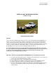
Veris Technologies Pub. #OM 1CM02-1 VERIS 3100 SOIL EC MAPPING SYSTEM (software v.1.76g) OPERATING INSTRUCTIONS Warranty Veris Technologies warrants this product to be free of defects in materials and workmanship for a period of one (1) year from the date of delivery to the purchaser. Veris Technologies will repair or replace any product returned to Salina, Kansas, which appears upon inspection to be defective in materials or workmanship.
Veris Technologies Pub. #OM 1CM02-1 Installation and Set-up Instrument The Veris EC Instrument Kit (PN 15161) includes the following: Signal cable Protective case Power Cable Test Load Test Box Mounting Bracket EC Instrument Make sure that you have received all of these components in your EC Package. Mount instrument in a location that is as free as possible from dust, vibration, and electrical interference. Display should be visible to operator and shielded from direct sunlight.
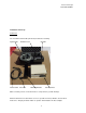
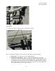
Veris Technologies Pub. #OM 1CM02-1 Below is a rear view of the instrument Serial Port for GPS Signal Serial Port for Listening Computer Power Power cable Switch Port Signal Port For signal cable or Test Load Connect GPS cable to GPS INPUT serial port on back of instrument. The Veris instrument is designed to accept GPS input in NMEA format via an RS232 connector. Note: GPS signals are frequently affected by electrical interference from magneto electrical systems.
Veris Technologies Pub. #OM 1CM02-1 Test Load Note: It is advisable to conduct this test as a routine check to ensure that you are obtaining reliable data. Note: This equipment has been tested and found to comply with the limits for a Class A digital device, pursuant to Part 15 of the FCC rules. These limits are designed to provide reasonable protection against harmful interference when the equipment is operated in a commercial environment.
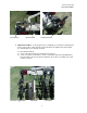
Veris Technologies Pub. #OM 1CM02-1 Support here 3) Install tongue with two 5/8’ X 41/2” bolts and torque to 170 ft lbs Prior to operating the implement for the first time, it is important to check the following: 1) All fasteners – some may have loosened during shipment. 2) Coulter electrode isolation – check so see that no metal part of the any coulter electrode is in contact with the implement frame.
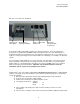
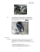
Veris Technologies Pub. #OM 1CM02-1 No continuity Grounded Bolt Coulter terminal 3) Implement Test Box – To properly measure conductivity, good electrical continuity must be present from the coulter electrode to the instrument. The Implement Test Box (Part No. 10759) allows you to quickly check this. Use the following method: a) Connect the signal cable to the terminal on the test box.
Veris Technologies Pub. #OM 1CM02-1 c) Continue to check each coulter electrode in succession, left to right. d) If any coulter electrode exhibits no continuity or resistance higher than 2 ohms, refer to the maintenance or trouble shooting sections for possible causes. Note: It is advisable to perform this test on a routine basis (weekly or every 20-25 hours of data collection) to ensure you are obtaining reliable data.
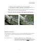
Veris Technologies Pub. #OM 1CM02-1 Pivot grease zerks Rachet jack -- 40 hour intervals grease zerks Electrode coulters Pivot -- In all but the most extremely rocky conditions, the coulter electrodes should not flex in the field, thus minimal movement will be realized at the pivot. 80-hour intervals should be sufficient.
Veris Technologies Pub. #OM 1CM02-1 grease zerk Hubs -- Use good quality wheel bearing or lithium grease for lubrication, but we suggest that you grease the hubs sparingly. Over-lubricating the hub will result in pre-mature seal failure, and an excessive amount of grease in the hub cap/commutator. On an interval of 150 hours, 1-2 strokes of grease should be sufficient. Grease zerk ADJUSTMENTS Commutators-- The spring-loaded commutators are located in the center of each coulter electrode hub cap.
Veris Technologies Pub. #OM 1CM02-1 4) If the plunger will not move freely, replace, and coat with di-electric silicone grease. 5) If the commutator appears to be in good working order, reinstall in the hub, and adjust until it bottoms against the spindle end. Rotate 1/2 turn backward to allow adequate clearance. Improper adjustment will result in premature failure (too little tolerance) or poor continuity (too much tolerance). 6) Reinstall locking set screw and tighten firmly on top of commutator.
Veris Technologies Pub. #OM 1CM02-1 Coulter electrode hubs -- The coulter electrode hubs operate in a significantly harsh environment, and annual inspection is of utmost importance. The double-lip seals are designed to keep grease in, and contaminates out, but they are the cause of practically all hub failures. It is advisable to disassemble, clean, repack, and re-install annually.
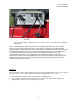
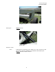
Veris Technologies Pub. #OM 1CM02-1 Field Operations Soil Contact Begin field operation by lowering unit into soil. For good electrical conductivity, all coulter electrodes must be in direct contact with the soil, at all times and in every region of the field. A depth of 1-2” is recommended. To insure this depth is consistently achieved, 400-600 lbs. of additional weight are normally required. Veris offers optional weights, or they can be supplied by the customer.
Veris Technologies Pub. #OM 1CM02-1 Signal Cable Attach the signal cable to the quick connect coupler at front of frame, and to Signal Port on back of instrument Instrument display readings Here are the display readings that you will see when operating the system, the meaning of each, and what choices you have at each step: Booting up… Veris v1.76e You have ______min. available Press any key Meaning: The unit is ready to operate.
Veris Technologies Pub. #OM 1CM02-1 1. Begin data acquisition 2. Conductivity Output Only 3. Quit Meaning: The unit is asking whether you’re ready to start mapping. Choices: If you press 1, you’ve initiated the beginning of a map file. Command #2 is for sending a data string to a second data-logging device. (The conductivity output format is 9600 baud, 8 data bits, no parity and 1 stop bit. A null modem adapter is required.) If you press 3, the system will tell you it’s ok to shut off power.
Veris Technologies Pub. #OM 1CM02-1 Meaning: You can do four different things with the file you have just created: Option 1: Download to disk. If you press the #1 button, you will be asked to insert a diskette in the disk drive and begin downloading the file. Option 2: Delete the file. If you press the #2 button, you will be asked if you really want to delete the file, as a safeguard against accidentally deleting files.
Veris Technologies Pub. #OM 1CM02-1 Downloading/deleting old files… This section deals with how to download and delete old files. Veris Technologies recommends that you do not delete any old files until they have been saved to a hard disk drive and properly backed up. Once you have done this, it’s a good idea to delete the files from the Veris instrument.
Veris Technologies Pub. #OM 1CM02-1 If you choose to quit, the display will read: Ok to shut off power Press any key to restart TROUBLESHOOTING Map doesn’t match known or expected soil types -1. 2. 3. 4. Check electrical continuity using Implement Test Box as discussed on Page 6. Check isolation of coulter electrodes (pg. 5) Map additional fields to see if similar condition results Contact Veris Service Department No conductivity readings on instrument display-1. 2. 3. 4.
Veris Technologies Pub. #OM 1CM02-1 2. Check to see if you are receiving DGPS signal; system eliminates all non-DGPS geo-referenced points 3. Restart computer and try again 4. Try another diskette. 5. Use Rescue Disk (Veris part #12330) to download files. Follow instructions on Rescue Disk label. Time or date on instrument display is incorrect or needs to be reset for new time zone-1. Insert Time Set Disk (Veris part #-12331) to adjust time or date. Follow instructions on Time Set Disk.
Veris Technologies Pub. #OM 1CM02-1 At this point, upon clicking ok, legible strings of GPS data should begin appearing on the laptop screen. Here’s an example of a typical set of strings: $GPGGA,191528.00,3851.0333,N,09737.2342,W,2,08,1.3,372.7,M,27.3,M,10.0,0100*69 $GPGSA,A,3,09,23,21,17,08,01,03,29,,,,,2.6,1.3,2.3*39 $GPRMC,191528.00,A,3851.0333,N,09737.2342,W,0.1,0.0,090998,6.3,E*48 If GPS data doesn’t appear, recheck the port and configuration settings to make sure they are correct.
Veris Technologies Pub. #OM 1CM02-1 Select the communication port you are using on the PC and click OK: Use the following settings: 19200 Baud, 8 data bits, parity = none, 1 stop bit, flow control = none.
Veris Technologies Pub. #OM 1CM02-1 Select File from the drop-down menus; select the Properties button. Click the Settings tab at the top of the window that appears: Click on the ASCII Setup button at the bottom of the window. The following window will appear: Make sure the box beside “Append line feeds to incoming line ends” is checked. Click OK to close the ASCII Setup box, then OK to close the properties box. Select the File drop down menu again, and click on save.
Veris Technologies Pub. #OM 1CM02-1 Select #2 for transferring files through the serial port. The next screen will display information about the files with the given file number. Press any key to see options for the files. In this menu, selecting (1) will continue to the transfer process. (2) will ask the user to confirm their choice to delete the file. (3) will retain the files in memory and continue to the next sequential file number in memory. (4) will exit to the main menu.
Veris Technologies Pub. #OM 1CM02-1 If you do not see text scrolling down the screen, wait for the instrument to finish sending data, shut off the instrument, close the HyperTerminal session, reopen it and turn the instrument back on. Repeat the steps above to try to transfer the file again. When the text stops scrolling and the instrument indicates that the transfer is finished, select the Transfer drop down menu, click on Capture Text, and click Stop. This ends the file capture for that particular file.