Veris Technologies Pub. #OM 1CM02-1 2000XA Soil EC Mapping System Operating Instructions Table of Contents P. 3-7 Installation and set-up P. 7-12 Maintenance and Lubrication P. 12-17 Field Operations P.
Veris Technologies Pub. #OM 1CM02-1 VERIS 2000XA SOIL EC MAPPING SYSTEM (software v.1.76 alt) ) OPERATING INSTRUCTIONS Warranty Veris Technologies warrants this product to be free of defects in materials and workmanship for a period of one (1) year from the date of delivery to the purchaser. Veris Technologies will repair or replace any product returned to Salina, Kansas, which appears upon inspection to be defective in materials or workmanship.
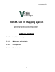
Veris Technologies Pub. #OM 1CM02-1 Installation and Set-up Instrument The Veris EC Instrument Kit (PN 15161) includes the following: Signal cable Protective case Power Cable Test Load Test Box Mounting Bracket EC Instrument Make sure that you have received all of these components in your EC Package. Mount instrument in a location that is as free as possible from dust, vibration, and electrical interference. Display should be visible to operator and shielded from direct sunlight.
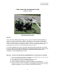
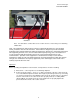
Veris Technologies Pub. #OM 1CM02-1 Below is a rear view of the instrument Serial Port for GPS Signal Serial Port for Listening Computer Power Power cable Switch Port Signal Port For signal cable or Test Load Connect GPS cable to GPS INPUT serial port on back of instrument. The Veris instrument is designed to accept GPS input in NMEA format via an RS232 connector. Note: GPS signals are frequently affected by electrical interference from magneto electrical systems.
Veris Technologies Pub. #OM 1CM02-1 Test Load Note: It is advisable to conduct this test as a routine check to ensure that you are obtaining reliable data. Note: This equipment has been tested and found to comply with the limits for a Class A digital device, pursuant to Part 15 of the FCC rules. These limits are designed to provide reasonable protection against harmful interference when the equipment is operated in a commercial environment.
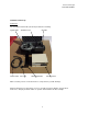
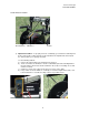
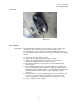
Veris Technologies Pub. #OM 1CM02-1 Coulter Electrode Isolation Grounded bolt Ohmmeter Coulter 3) Implement Test Box – To properly measure conductivity, good electrical continuity must be present from the coulter electrode to the instrument. The Implement Test Box (Part No. 15231) allows you to quickly check this. Use the following method: a) Connect the signal cable to the terminal on the test box.
Veris Technologies Pub. #OM 1CM02-1 Note: It is advisable to perform this test on a routine basis (weekly or every 20-25 hours of data collection) to ensure you are obtaining reliable data. 4) Hitch height—adjust hitch on implement so implement operates level when coulter electrodes are 1-2” in the soil. The hitch is designed with four possible height positions.
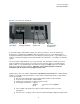
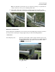
Veris Technologies Pub. #OM 1CM02-1 Rachet jack -- 40 hour intervals Grease zerks Electrode coulters Pivot -- In all but the most extremely rocky conditions, the coulter electrodes should not flex in the field, thus minimal movement will be realized at the pivot. 80-hour intervals should be sufficient. Grease zerk Hubs -- Use good quality wheel bearing or lithium grease for lubrication, but we suggest that you grease the hubs sparingly.
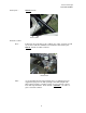
Veris Technologies Pub. #OM 1CM02-1 Coulter Hub Grease zerk ADJUSTMENTS Commutators-- The spring-loaded commutators are located in the center of each coulter electrode hub cap. They are factory preset, and should not need routine adjustment. If a continuity test shows abnormally high resistance, the commutators should be checked. This may be performed in the following manner: 1) Remove the 3/8” allen head set screw. 2) Remove the commutator by turning counter-clockwise.
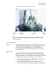
Veris Technologies Pub. #OM 1CM02-1 Here is a cut away view of the hubcap assembly Cap Commutator Set screw Spindle Note: If you are still unable to obtain favorable resistance readings, check for excessive corrosion at the coulter blade mounting bolts, or the terminal located near the coulter pivot. ANNUAL MAINTENACE Wheel hubs -- Coulter electrode hubs -- On and annual basis, disassemble, clean, and properly repack the wheel hubs with suitable wheel bearing grease.
Veris Technologies Pub. #OM 1CM02-1 4) 5) 6) 7) 8) 9) hub and do not mix bearings between hubs. Natural wear will cause the bearing and race to form pattern that is unique to that set. Thoroughly wash hub and bearings in solvent and dry. Replace bearings and races that show excessive wear or pitting. Pack with grease, and reassemble -- or reassemble, and pack via grease zerk with wheel bearing or lithium grease. It is advisable to replace the seals. Adjust bearing pre-load as mentioned above.
Veris Technologies Pub. #OM 1CM02-1 Field Operations Soil Contact Begin field operation by lowering unit into soil. For good electrical conductivity, all coulter electrodes must be in direct contact with the soil, at all times and in every region of the field. A depth of 1-2” is recommended. To insure this depth is consistently achieved, 300-350 lbs. of additional weight are normally required. Veris offers optional weights and mounting hardware that can be installed on the 2000XA.
Veris Technologies Pub. #OM 1CM02-1 Wide Setting GPS Settings 1. Make sure that the GPS is plugged into the proper DB-9 input. Looking at the back of the instrument, the GPS should be plugged into the leftmost input port. A null modem adapter should not be used. 2. Make sure that the GPS has power and has been turned on long enough to start outputting data. Some units may require a couple minutes to start while others may require much longer. 3.
Veris Technologies Pub. #OM 1CM02-1 Signal Cable Attach the signal cable to the quick connect coupler at front of frame, and to Signal Port on back of instrument Instrument display readings Here are the display readings that you will see when operating the system, the meaning of each, and what choices you have at each step: Booting up… Veris v1.76 You have ______min. available Press any key Meaning: The unit is ready to operate.
Veris Technologies Pub. #OM 1CM02-1 Choices: If you press 1, you’ve initiated the beginning of a map file. Command #2 is for sending a data string to a second data-logging device. (The conductivity output format is 9600 baud, 8 data bits, no parity and 1 stop bit. A null modem adapter is required.) If you press 3, the system will tell you it’s ok to shut off power.
Veris Technologies Pub. #OM 1CM02-1 Option 4: Exit File Manager. If your press the #4 button, you will immediately go to data acquisition mode, and can then choose to begin or quit. If you selected Option 1 above, here is the next display you will see: Insert disk and press any key Meaning: The instrument is expecting to download the file. Choice: Insert disk, then press any key.
Veris Technologies Pub. #OM 1CM02-1 that you make while setting up or checking out the system, especially files with no data on them, such as those you make while testing the DGPS signal reception. At display: 1. Download / Delete old files 2. Continue Meaning: This is the second window you will see after powering up the unit, once the system has any old files on it. Options: 1.
Veris Technologies Pub. #OM 1CM02-1 TROUBLESHOOTING Map doesn’t match known or expected soil types -1. 2. 3. 4. Check electrical continuity using Implement Test Box as discussed on Page 5). Check isolation of coulter electrodes (pg. 4) Map additional fields to see if similar condition results Contact Veris Service Department No conductivity readings on instrument display-1. 2. 3. 4. No continuity on coulter electrode # 1 or # 4. Check for excessive corrosion on coulter terminal.
Veris Technologies Pub. #OM 1CM02-1 1. Insert Time Set Disk (Veris part #-12331) to adjust time or date. Follow instructions on Time Set Disk. Troubleshooting GPS Problems-This is a problem-solving guide for the user who is not able to obtain a position from the GPS when it is connected to the Veris 3100 instrument.
Veris Technologies Pub. #OM 1CM02-1 what adjustments (connectors or software) are necessary to bring the signal into a computer. On the other hand, if the signal appears correctly on HyperTerminal and it shows that the required strings are being output, retry the unit with the Veris instrument. If it still doesn’t work, please call Veris at 785-825-1978 to see how we can help solve the problem.