AcquiSuite EMB – Data Acquisition Server Obvius, LLC Installation and Operation Manual Model A8810 Date Jul 28, 2010 Page 1 A8810 AcquiSuite – Data Acquisition Server
Copyright Information Copyright © 2001 - 2010 by Obvius Obvius and AcquiSuite are trademarks of Obvius Holdings LLc Other brand and product names are trademarks or registered trademarks of their respective holders. U.S. Government Restricted Rights: Use, duplication or disclosure by the Government is subject to restrictions set forth in subparagraph (a) through (d) of the Commercial Computer Restricted Rights clause at FAR 52.
Table of Contents Overview....................................................................................................................................................................................................... 4 Installation Checklist..................................................................................................................................................................................... 4 Markings and Symbols:.........................................................
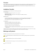
Overview The AcquiSuite™ data acquisition system is designed to allow owners and managers of commercial and industrial facilities with a cost-effective means of gathering crucial information in a timely manner. To meet these requirements, the AcquiSuite™ system provides the installer with all the tools necessary to install and configure the hardware and software with a minimum of time and investment.
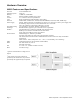
Hardware Overview A8810 Features and Specifications Processor Operating System Memory LED Console LAN Protocols Power Supply Interval Recording Serial Port1 Isolation2: Environmental Safety EMC Size Mass Arm9 embedded CPU Linux 2.
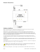
Electrical Connections Hardware Installation Step 1 - Unpack materials: Remove all materials from shipping box and verify all required components are available Step 2 - Mount the AcquiSuite on the wall, panel or other appropriate location. Step 3 (optional) - Connect the Modbus network loop as shown in the wiring diagram. Follow the manufacturer’s instructions for installing and powering the Modbus devices. Verify that the Modbus address settings are unique for each device (i.e.
installer to provide the required 24VDC. After power is applied, the green “Alive” light in the upper right of the AcquiSuite should come on and the LCD display will display a series of diagnostic screens ending with the following message on the LCD display (this boot sequence may require up to 20 seconds to complete): AcquiSuite Ready 192.168.40.50 This indicates that the AcquiSuite has loaded properly and is ready for configuration and connection to the network and sensors.
(Note: A “device” is the Modbus connected device, not necessarily the sensor. For example, an A8332-8F2D I/O module with 8 sensors connected is only one modbus device, not eight) For further information on the LCD console, please review the console section of this manual. E. The AcquiSuite completes a background scan for new Modbus devices every 2-5 minutes. Increasing the RS485 Modbus timeout may increase the time required to detect new devices.
C. Press the select button again to see the IP address menu: [IP Address] 192.168.40.50 D. At this point, the cursor on the display will be blinking on the first number in the IP address on the second line. E. To change the number, press the menu (top) button and the display will cycle through the digits 0-9 as well as “.”. Once the correct digit is displayed, press the select (lower) button to advance to the next digit and repeat the process until all the digits are correct. F.
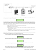
If the Laptop is to be attached to an existing LAN, obtain a static IP address (or use DHCP addressing) from the network administrator. Static IP Address for the laptop Specify an IP address IP address: ___.___.___.___ Netmask: ___.___.___.___ DHCP Direct Connection to Laptop Obtain an IP address automatically. IP Address: 192.168.40.1 (All other required settings are assigned Netmask: 255.255.255.
AcquiSuite Administration Overview The AcquiSuite should now be available on the local area network for you to access using a web browser such as Internet Explorer or Netscape. Step 1 - Use your web browser to connect to the AcquiSuite by entering http://192.168.40.50/setup/ Where 192.168.40.50 is the IP address displayed on the on the AcquiSuite LCD display.
Security The AcquiSuite has three levels of security. These are “operator”, “user” and “admin”. When using a browser to access the AcquiSuite, basic http authentication is used to prompt your browser for a username and password. The admin account uses “admin” as the default password. To change the password, select the Accounts menu from the left side tree display. Next, select the account name. Click the “Change Password” button to set a new password for the selected account.
Device List Options At the top of the Modbus device list page, there are several display options that control the sorting of the device list. Tree display: Click this icon to organize the list by showing each ModHopper, and the devices attached to each one. List display: (default) Show the list of Modbus devices sorted by the Modbus address number. At the bottom of the Modbus device list, there are several options that may be selected to view or configure all the Modbus devices at the same time.
Device Details. The device detail page will show a list of all the meter data points, alarm settings and console options. The data point names for most devices are automatically entered. Some devices such as the A8332-8F2D io module have generic inputs, and will be labeled as “Input #1”. At the top of the page, the status of the device is shown. This usually reports “ok” however it can include error information if the device is not responding properly.
Manual Device Add Options Modbus devices may be added manually by clicking on the “add” link on the bottom of the Modbus device list page. This option is intended for use when adding devices to the configuration profile prior to installing the physical hardware, or configuring Modbus/TCP devices that will not automatically populate in the Modbus device list. The manual setup page has several options that must be configured before the AcquiSuite will recognize the Modbus device.
Troubleshooting Modbus Devices If the device you have attached does not appear in the Modbus device list, check the following: ● Verify the + (red), - (black), and Shield connections are correct on all connections. Look for any connection in the middle of the loop that may have the wires reversed, or shorted together. Check the Modbus faq on the obvius.com website for further details on wiring a Modbus serial connection. ● Verify the address settings of every Modbus device.
different baud rates. Modbus devices default to a baud rate of 9600. Note: Modbus device manufacturers usually do not 'officially' support this configuration, however we have not seen any problems with this in any of the Modbus devices we provide drivers for. Most Modbus devices simply ignore packets received at the wrong baud rate. If you are experiencing Modbus communications problems, you should set the baud rate to a fixed 9600 before troubleshooting.
Modbus Framework The Modbus Framework feature is a tool to allow the AcquiSuite to read data from any Modbus device by creating a template in the Modbus Framework editor. The template describes the Modbus register read commands, and the conversion required for each data point that is to be read. The Framework feature is an advanced feature of the AcquiSuite that requires the user to be familiar with the Modbus protocol and with the Modbus register point list for the specific Modbus device that will be used.
Networking Network Status This page displays the current status of the AcquiSuite network connections. Several interfaces may be shown if both Ethernet and ppp dialin/dialout are active at the same time. Each interface will report the ip address, number of packets sent and received, and other details specific to the interface. For the ethernet interface, the MAC address (HWaddr) will be shown as well as a network collision count.
● Use the LCD console to run the Network Status test. This will attempt a number of things including a ping query to the gateway address. If the AcquiSuite can ping an external machine such as a gateway, the ethernet port is most likely connected properly. If the AcquiSuite does not use a gateway, try adding a gateway address, and make it the address of your computer. System Options Status The system status page shows the current memory and flash disk utilization values, system up-time, and load average.
convert the information when generating a report for the user. For example, if you wish to draw a graph of KW over Time, prompt the user for a date range, say Jan 1 midnight to Jan 2 midnight. Take the user specified end points and convert these times from Local time to UTC. Next, create an SQL query using the new UTC formatted data as your select statement. ie: SELECT * from TABLE where time > '2003-01-01 08:00:00' and time < '2003-01-02 08:00:00' Note the time is 8 hours ahead of local time.
zImage The Linux operating system. When clicking on the Upgrade button, the AcquiSuite will again contact the obvius.com website and download the requested firmware image file. The AcquiSuite will take a few seconds to verify the file checksum and prompt you with an “Install” button. Click the install button and the AcquiSuite will install the firmware update and reboot itself to make the changes take effect. Do not power down the AcquiSuite during any step of the AcquiSuite firmware update process.
Note in the last section where SUCCESS is indicated. The failure is due to the password not being correct. LCD Console The AcquiSuite has an LCD console and two push buttons labeled “menu” and “select”. These can be used to configure some of the basic features of the AcquiSuite. The intended purpose of the console is to configure the AcquiSuite to a point where a computer can communicate with it for further detailed configuration.
Note: selecting the modbus status option from the AcquiSuite console does not cause the AcquiSuite to search for new devices. The AcquiSuite checks for new devices in the background all the time, taking about 2.5 minutes to complete each pass through all 255 possible addresses. The modbus test console option simply displays the number of devices the AcquiSuite presently knows about.
a 4A4P-M IO Module. '2002-01-31 18:30:00',0,0,0,-0.00,89.29,39.05,49.11,0,0,0,0 '2002-01-31 18:35:00',0,0,0x02,-0.01,104.24,39.05,49.11,0,0,0,0 '2002-01-31 18:40:00',0,0,0,,87.82,39.05,49.11,0,0,0,0 '2002-01-31 18:45:00',139,,,,,,,,,, In this example, the first line shows a regular log entry. The second line shows a high range alarm for data point 2. The third column shows point 1 as invalid, and the fourth line shows the Modbus device is not responding. Notice the following columns are shown. 1.
140 141 142 143 160 161 162 163 164 165 192 193 Received invalid modbus data checksum Received response from unexpected device Received unsolicited query, assume another modbus master device is present. Modbus device probe function received some good responses and some failures. Start log (Entry in log file after AcquiSuite starts up) Stop log (Entry in log file if AcquiSuite is shut down properly) System time changed, caused logger to restart logging for intervals. System auto-restart Log entry corrupt.
Step 1: First, use your browser to connect to the AcquiSuite. Select the Modbus/Setup section from the menu on the left. In the field titled "Modbus Loop Name" enter a name for this AcquiSuite to uniquely identify it on the BMO website. Because the BMO site can show multiple AcquiSuite devices, it is important to have a descriptive name in this field. Step 2: Select the “Log File Data”, “Setup/Upload” menu option.
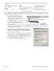
HTTP Direct from the AcquiSuite The AcquiSuite has the ability to export log file data to a web browser directly from the setup web pages. To use this feature, access the AcquiSuite setup menu with your web browser. Select the "Log File Export" page from the Log File Data menu on the left side of the page. For each device, a separate log file will be saved. Select the device from the dropdown list provided. Specify Comma or Tab delimited data, and indicate if column headers are required.
For FTP, the process is essentially the same process as the manual FTP data download. For more information on FTP access to the AcquiSuite, please view the FAQ and Technotes section of the Obvius.com website. Steps for Microsoft Windows command prompt ftp. Use the following commands. ftp 192.168.40.50 username: root password: admin cd /var/log/modbus dir mdel *.gz bye Use the IP address of your AcquiSuite The same as the admin password view a list of log files.
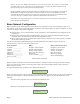
Mechanical Drawings The AcquiSuite uses a plastic enclosure that is approximately 4” x 4.25” x 2” deep. The AcquiSuite has 4 mounting holes for use with a #6 screw. The drawing above shows the relative position of the mounting holes.