
Install
Troubleshooting
Pulse count input troubleshooting:
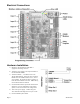
Verify the pulse output meter is connected to the GND and IN# terminals of the A8332-8F2D. (not the +24V terminal)
Use the OCC software or AcquiSuite configuration page. Verify the specific input mode is set to Pulse, Pulse-kyz, or Status.
Check the input LED for the specific input that is not working. The LED should blink when the pulse meter closes the
contact output. If the LED is not blinking, try bridging the input terminals with a short piece of wire to confirm the LED
comes on. Note: if the input LED lights up when you bridge the input terminals, the problem is likely with the meter, and/or
the wiring to the meter.
If the LED is always on, you may have a short in the wires leading to the pulse output meter. Try removing the wires from
the A8332-8F2D input to confirm the LED turns off. If so, repeat the test with the wires attached at the A8332-8F2D, and
disconnected at the pulse output meter.
Try bridging the terminals at the other end of the pulse wiring run. This will confirm there are no breaks in the wire.
Verify the pulse output device is operating.
Disconnect the A8332-8F2D input and use a hand held digital meter and measure resistance of the pulse output device.
Verify that the pulse output device is operational and the contact closure reads less than 1000 ohms when closed. For high
resistance pulse devices such as intrinsic barriers, the “contact closure threshold” register may need to be configured to a
larger value. The default is 1k however up to 2.5k is allowed. If using the OCC software or the AcquiSuite data acquisition
server, use the advanced configuration page of the A8332-8F2D in the Modbus/device list to set this option.
Analog 4-20mA input troubleshooting:
Verify the analog output sensor is connected to the proper terminals. For a 2 wire 4-20mA sensor, this is typically the +24
and IN# terminals of the A8332-8F2D.
Use the OCC software or AcquiSuite configuration page. Verify the specific input mode is set to 4-20mA mode.
Check the input LED for the specific input that is not working. The LED should be off for normal operation. If the sensor
reads below 4mA, the LED will show a blink-blink-off pattern. If the sensor is reading above 20mA, the LED will blink in a
fast (2Hz) pattern.
Use the OCC software to view the mA output reading for the channel.
Use a hand-held meter. Select the DC mA reading mode of the meter and wire the meter in series with the sensor output, and
the A8332-8F2D input terminal. Typically, the Red/+ meter probe connects to the sensor output wire, and the Black/- meter
probe connects to the IN# terminal of the A8332-8F2D. Verify the mA reading on your meter matches the OCC software
reading.
Analog 0-10V input troubleshooting:
Verify the analog output sensor is connected to the proper terminals. For a self-powered 2 wire 0-10V sensor, this is
typically the GND and IN# terminals of the A8332-8F2D. For a 3 wire device that uses power supplied by the A8332-
8F2D, all three input wires (GND, IN# and +24V) will be used.
Use the OCC software or AcquiSuite configuration page. Verify the specific input mode is set to 0-10V mode.
Check the input LED for the specific input that is not working. The LED should be off for normal operation. If the sensor is
reading above 10V, the LED will blink in a fast (2Hz) pattern.
Use the OCC software to view the voltage output reading for the channel.
Use a hand-held meter. Select the DC Volts reading mode of the meter and wire the meter in parallel with the sensor output;
this will use the Red/+ meter probe on the IN# terminal and the Black/- meter probe on the GND terminal. Verify the
voltage reading on your meter matches the OCC software reading.
Page 9 A8332-8F2D