
Install

Dipswitch Configuration
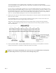
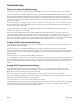
Modbus Address: Before the A8332-8F2D can be used, you must set the Modbus address
of the A8332-8F2D. This address must be unique among all Modbus devices in the
system. The A8332-8F2D supports address 1 through 127.
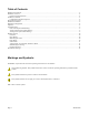
Select an address, and set the dipswitches to match.
The sum of the value of the switches is the address. In the example to the right, address 52
is set by placing switch 4, 16 and 32 to the on position.
Note: 4 + 16 + 32 = 52
Baud Rate: This option sets the serial port speed for the RS485 port. Set this option to
“off” for 19200. Set the switch to “on” for 9600 baud.
Operation
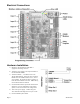
The device should power up and be ready in a few seconds. The LEDs should blink in the following manner.
● The green "Alive" LED should start to blink approximately once per second.
● The yellow RS485 TX and RX LEDs will blink for local Modbus activity.
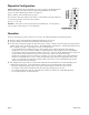
● For each input, you MUST configure the input mode register. [40065 – 40072]. The mode register sets up the input for
4-20mA, 0-10V, pulse, or resistance type sensors. The default mode is “unconfigured”. The following methods can be
used to configure each input. (you should choose only one method below)
• Use the AcquiSuite device configuration page, select configure point. Pick the appropriate mode from the
dropdown list. Also, you will need to configure each pulse input with a Name, Engineering Unit, and Multiplier.
• Use the Obvius Config Console software available at obvius.com. Select the A8332-8F2D from the list, and choose
the input mode from the dropdown list. Be sure to click the “Save” button at the bottom of the page.
• If neither the AcquiSuite or the OCC software are available, you can use any modbus register writing software or
hardware, such as ModScan32, or a PLC. Select the input mode register and write the appropraite value to that
register. For a complete list of registers, and allowed mode values, please review the Modbus Register Listing
section towards the end of this document.
● After configuring the input mode, the red input status LEDs will show information for each input depending on the
configured mode of the input.. Input status LEDs are adjacent to the corresponding input screw terminals.
• For inputs configured for pulse, pulse-kyz, and status, the LED will turn on when the contact is closed.
• For 4-20mA, 0-10V modes, the LED will show off-scale-high by blinking fast (2x second)
• For 4-20mA and Resistance mode, the LED will show a broken wire alarm with a blink-blink-off pattern.
• For unconfigured inputs, the LED will be off.
Page 8 A8332-8F2D