
Install
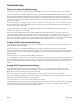

- If the A8332-8F2D receives any Modbus traffic on the RS485 port, the yellow RX led should blink.
- If the A8332-8F2D receives a Modbus query that is addressed to it specifically, the yellow TX LED should blink
and it will respond to the query.
If you are using an AcquiSuite Data Acquisition Server, the A8332-8F2D should appear in the Modbus device list
after about 2 minutes at the Modbus address set in step 4 above. Click on the device, and select “Configure” to give
the A8332-8F2D a logical name. This will allow the AcquiSuite to begin logging data for the device. If you are
using the Obvius Configuration Console, enter the Modbus address from step 4 above in the scan range field and
click scan. The A8332-8F2D should appear in the device list with that Modbus address.
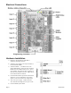
7) With the power disconnected, attach the pulse or analog input lines to the pulse terminals. Each input has a GND ,
Input#, and +24V terminal.
The A8332-8F2D provides 3-5 volts on the Input# terminal for sensing in pulse or contact closure mode. The
remote pulse output device must not supply voltage to the terminals.
Wiring runs to input terminals should be kept as short as possible. Wiring runs longer than 200 ft should be
avoided. Wiring should avoid proximity to sources of electrical noise such as running in parallel to electrical
cable, and VFD systems.
8) Power up the A8332-8F2D. The Alive LED should blink once per second. Use the AcquiSuite or the Obvius
Config Console software or AcquiSuite to confirm the operation of each input.
WARNING: After wiring the A8332-8F2D, remove all scraps of wire or foil shield from the electrical panel.
This could be dangerous if wire scraps come into contact with high voltage wires.
Page 7 A8332-8F2D