
Install
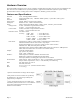
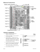
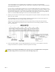
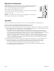
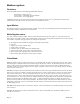

Table of Contents
Markings and Symbols:...............................................................................................................................................................3
Hardware Overview.....................................................................................................................................................................4
Features and Specifications....................................................................................................................................................4
Installation Checklist...................................................................................................................................................................5
Configuration Software Required:.........................................................................................................................................5
Electrical Connections.................................................................................................................................................................6
Hardware Installation...................................................................................................................................................................6
Dipswitch Configuration..............................................................................................................................................................8
Operation.....................................................................................................................................................................................8
Troubleshooting...........................................................................................................................................................................9
Pulse count input troubleshooting:.........................................................................................................................................9
Analog 4-20mA input troubleshooting:.................................................................................................................................9
Analog 0-10V input troubleshooting:....................................................................................................................................9
Modbus registers........................................................................................................................................................................10
Functions..............................................................................................................................................................................10
Input Modes: .......................................................................................................................................................................10
Mode Register value:...........................................................................................................................................................10
Pulse Mode:.........................................................................................................................................................................10
Status Mode:........................................................................................................................................................................11
Voltage Mode, Current Mode, Resistance Mode: ..............................................................................................................11
Modbus Register Listing......................................................................................................................................................12
Register Functions................................................................................................................................................................14
Mechanical Drawings................................................................................................................................................................15
Markings and Symbols:
WARNING: A potential risk exists if the operating instructions are not followed
General Warning Symbol: This symbol indicates the need to consult the operating instructions provided with the
product.
This symbol indicates the presence of electric shock hazards.
This symbol indicates: Do not apply to or remove from hazardous live conductors.
Direct Current symbol.
Page 3 A8332-8F2D