
Install
1025 41026 UINT16 power supply voltage monitor. scale: x100, volts
1026 41027 INT16 pcb temperature monitor. scale: x100, degrees F.
1027 41028 UINT16 5V internal power supply voltage monitor. scale: x100, volts
1028 41029 UINT16 RS485 baud rate. 2=9600, 3=19200.
1029 41030 UINT16 relay output 1 mode. (R/W, NV) 0=manual, 1=follow pulse input #1.
Note: input must be in pulse or status mode.
1030 41031 UINT16 relay output 2 mode. (R/W, NV) 0=manual, 1=follow pulse input #2.
Note: input must be in pulse or status mode.
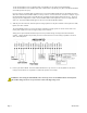
Modbus function 0x11 Slave ID response will report the following:
"Obvius, A8332-8F2D, IO Module, 8-Flex, 2-DO", id=48
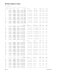
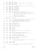
Register Functions
Pulse Count: The pulse count is stored as an unsigned 32bit integer. This allows for 2^32 pulses (4.2billion) to be counted
before rollover. On Modbus systems that do not allow you to read 32bit values, you can calculate the pulse count as
follows:
count = (MSW * 65535) + LSW
Pulse count registers accumulate a total number of pulses received on each pulse input. The pulse count totals always
increment and can not be cleared or set to an arbitrary value to prevent tampering. All pulse count totals are stored in non-
volatile memory to preserve counts during power failure. The unsigned 32 bit counter values can accumulate up to 4.29
billion (2^32) pulses before rollover.
All 32 bit data point values are encoded in 2 Modbus registers (16bits each). Modbus master systems should always query
the A8332-8F2D using a single query to read an entire block of registers. Never use two queries to read one register and
then combine the two results into a single 32 bit value. Doing so will allow the pulse count to increment in the middle of
the two Modbus queries, and will cause intermittent data readings that are incorrect.
For example, a pulse input has a count of 65534. This is represented as a 32 bit hex number 0x0000FFFE. The first 4 digits
are the MSW register, the second 4 digits are the LSW register. The Modbus Master reads the first (MSW) register and gets
0x0000. In between the two readings, the pulse input counts 2 more pulses, making the total 65536 or 0x00010000 in hex.
Next the Master reads the second (LSW) register and gets 0x0000. When the two registers are combined, the result is
0x00000000. The proper way to handle this situation is to simply read both registers in a single Modbus query.
Page 14 A8332-8F2D