
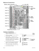
Install
Modbus registers
Functions
The A8332-8F2D responds to the following Modbus/RTU functions:
function 0x11 Report slave id.
function 0x03 read holding registers (multiple)
function 0x06 preset single register
All Modbus registers are read-only unless otherwise noted. Registers listed as “NV” are options that are stored in non-
volatile memory and will be preserved when power is removed from the device.
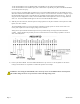
Input Modes:
Each of the 8 inputs has several different modes (4-20mA, 0-10v, pulse, etc) The following sections list the purpose of each
of the Modbus registers depending on the selected mode.
Mode Register value:
The value of the mode register (40065 - 40072) controls the mode of the input (volts, pulse, etc). Users may write to the
mode register, and it will be stored in non-volatile memory. Note however that the preferred operation is to use the OCC tool
or the A8812 AcquiSuite web page interface to configure the input mode.
0 = unconfigured (return 0xFFFF for all registers associated with this input)
1 = reserved.
2 = Analog current mode, 4-20mA range.
3 = voltage mode, 0-10v range.
4 = resistance mode, as ohms measured. 0-10Mohm range.
5 = contact closure mode, reports closure count and dutycycle.
6 = pulse counter input. (standard) counts contact closures only.
7 = pulse counter input. (KYZ mode) counts closure and open.
Pulse Mode:
count: the number of pulses counted on the input port. In standard mode, the pulse is counted on the closure of the contact.
If the KYZ option is enabled, both the closure and opening of the pulse are counted. The maximum pulse rate to be able to
count is 10 Hz. Expect pulse width to be minimum of 20ms. The pulse count starts at zero (factory default) and always
increments as pulses are counted. Rollover at 2^32 (approx 4.3 billion). Count is stored in non-volatile memory. The pulse
count can not be reset to zero.
rate-inst: This register reports the instantaneous rate of pulses received on the input, calculated based on the time the last N
pulses were received. For example, if the pulse rate is 2Hz, and N is 5, then 5 pulses will be received in 10 seconds, and the
rate-inst value will return 10. N is user selectable from 2 to 20. Note: as the value of rate-inst increases, the pulse rate it
represents decreases. thus, a value of 20(seconds) represents a pulse rate that is 1/2 of a 10s value. If the pulse rate is very
fast such that rate-inst < N the value of rate-inst will be unusable due to the granularity of the measurement. This should be
handled as off-scale-high by the Modbus master system. To properly handle this situation, reconfigure the pulse output
meter with a slower pulse rate using a larger multiplier. The rate-inst register will report 65535 when off-scale-low. When
reading large values from rate-inst, it is advisable to handle numbers as off-scale-low when the number of seconds exceeds
the data logging interval.
rate-min: The minimum rate value as measured in rate-inst. Note: the minimum rate is actually the largest count of seconds
seen in rate-inst.
rate-max: The maximum rate value as measured in rate-inst. Note: the maximum rate is actually the smallest count of
seconds seen in rate-inst.
Page 10 A8332-8F2D