A8332-8F2D Modbus Flex IO Module Obvius, LLC Installation and Operation Manual Date May 29, 2009 Page 1 A8332-8F2D
Copyright Information Copyright © 2008 - 2009 by Obvius Obvius and AcquiSuite are trademarks of Obvius Holdings LLc Other brand and product names are trademarks or registered trademarks of their respective holders. U.S. Government Restricted Rights: Use, duplication or disclosure by the Government is subject to restrictions set fourth in subparagraph (a) through (d) of the Commercial Computer Restricted Rights clause at FAR 52.
Table of Contents Markings and Symbols:...............................................................................................................................................................3 Hardware Overview.....................................................................................................................................................................4 Features and Specifications.....................................................................................................
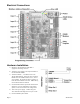
Hardware Overview The A8332-8F2D is designed to read a variety of industry standard analog and pulse sensor devices and communicate the data values back to a Modbus master system using RS485. Applications include data acquisition systems reading gas/water/electric meters or analog sensors such as temperature, humidity, pressure, and flow. Features and Specifications Processor LED Protocols Power Supply Serial Port1 Inputs1 Voltage mode: Arm7, field upgradeable firmware.
Installation Checklist The following components are required for a complete A8332-8F2D I/O module installation: ● ● ● ● ● ● ● ● ● ● A8332-8F2D I/O module Screwdriver for terminals: 2.4mm slot/straight or equivalent. Obvius Configuration Console software. A computer with an RS232 or RS485 port and a serial cable, or a USB to serial adapter. Modbus/RTU master device such as an AcquiSuite™ A8812 server Pulse or analog output device Power supply: 24VDC Wire.
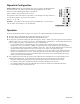
Electrical Connections Hardware Installation 1) Mount the A8332-8F2D on a DIN-Rail or appropriate mounting enclosure. 2) Attach the power supply to the input terminals on the A8332-8F2D module. 3) Attach the RS485 +, - and shield wires to the A8332-8F2D module. Attach the other end of the RS485 line to the Modbus master device, such as an AcquiSuite. Be careful to observer polarity on both ends of the RS485 connection. RS485 wiring runs should be limited to 4000 ft.
- If the A8332-8F2D receives any Modbus traffic on the RS485 port, the yellow RX led should blink. - If the A8332-8F2D receives a Modbus query that is addressed to it specifically, the yellow TX LED should blink and it will respond to the query. If you are using an AcquiSuite Data Acquisition Server, the A8332-8F2D should appear in the Modbus device list after about 2 minutes at the Modbus address set in step 4 above. Click on the device, and select “Configure” to give the A8332-8F2D a logical name.
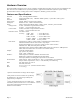
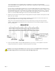
Dipswitch Configuration Modbus Address: Before the A8332-8F2D can be used, you must set the Modbus address of the A8332-8F2D. This address must be unique among all Modbus devices in the system. The A8332-8F2D supports address 1 through 127. Select an address, and set the dipswitches to match. The sum of the value of the switches is the address. In the example to the right, address 52 is set by placing switch 4, 16 and 32 to the on position.
Troubleshooting Pulse count input troubleshooting: Verify the pulse output meter is connected to the GND and IN# terminals of the A8332-8F2D. (not the +24V terminal) Use the OCC software or AcquiSuite configuration page. Verify the specific input mode is set to Pulse, Pulse-kyz, or Status. Check the input LED for the specific input that is not working. The LED should blink when the pulse meter closes the contact output.
Modbus registers Functions The A8332-8F2D responds to the following Modbus/RTU functions: function 0x11 Report slave id. function 0x03 read holding registers (multiple) function 0x06 preset single register All Modbus registers are read-only unless otherwise noted. Registers listed as “NV” are options that are stored in nonvolatile memory and will be preserved when power is removed from the device.
* clear min/max (register 41021): The Modbus registers for rate-inst, rate-min and rate-max may be cleared by writing to a Modbus register. It is assumed that these three fields will be cleared at the beginning of each new logging period by the Modbus master device. In pulse mode, clearing the inst register does not clear the pulse count history. The fields for inst/min/max will be valid after only one pulse value is received.
Modbus Register Listing Data points: ------- ------- ------- -----------------offset 0 1 2 3 4 5 6 7 8 9 10 11 12 13 14 15 point 40001 40002 40003 40004 40005 40006 40007 40008 40009 40010 40011 40012 40013 40014 40015 40016 type UINT32 UINT32 UINT32 UINT32 UINT32 UINT32 UINT32 UINT32 UINT32 UINT32 UINT32 UINT32 UINT32 UINT32 UINT32 UINT32 desc input input input input input input input input input input input input input input input input 1 1 2 2 3 3 4 4 5 5 6 6 7 7 8 8 modes--> Pulse value MSW (count/
59 60 61 62 63 40060 40061 40062 40063 40064 UINT32 UINT32 UINT32 UINT32 UINT32 input input input input input 6 7 7 8 8 max max max max max LSW MSW LSW MSW LSW 64 65 66 67 68 69 70 71 40065 40066 40067 40068 40069 40070 40071 40072 UINT16 UINT16 UINT16 UINT16 UINT16 UINT16 UINT16 UINT16 input input input input input input input input 1 2 3 4 5 6 7 8 mode mode mode mode mode mode mode mode 72 73 40073 40074 UINT16 UINT16 input status bitmap.
1025 1026 1027 1028 1029 41026 41027 41028 41029 41030 UINT16 INT16 UINT16 UINT16 UINT16 1030 41031 UINT16 power supply voltage monitor. scale: x100, volts pcb temperature monitor. scale: x100, degrees F. 5V internal power supply voltage monitor. scale: x100, volts RS485 baud rate. 2=9600, 3=19200. relay output 1 mode. (R/W, NV) 0=manual, 1=follow pulse input #1. Note: input must be in pulse or status mode. relay output 2 mode. (R/W, NV) 0=manual, 1=follow pulse input #2.
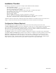
Mechanical Drawings DIN-Rail (EN50022) mount package: Width 105mm (6 modules) 3.39in 86mm LED 1 GND IN 3 +24V LED 3 GND IN 4 +24V LED 4 GND IN 5 +24V LED 5 485 RX 485 TX A8332-8F2D Shield RS485RS485+ Out 2 Out 1 Rev A GND IN 7 +24V LED 7 GND IN 8 +24V LED 8 GND IN 6 +24V Modbus Address LED 6 4.13in 105mm GND IN 2 +24V +24V GND LED 2 GND IN 1 +24V Alive Power Input 1 2 3 4 5 6 7 8 Relay Out 1 Relay Out 2 1.