K7VT4-4X K7VT4-8X User Manual Version 3.1 Published July 2003 Copyright©2003 ASRock INC. All rights reserved.
Copyright Notice: No part of this manual may be reproduced, transcribed, transmitted, or translated in any language, in any form or by any means, except duplication of documentation by the purchaser for backup purpose, without written consent of ASRock Inc. Products and corporate names appearing in this manual may or may not be registered trademarks or copyrights of their respective companies, and are used only for identification or explanation and to the owners’ benefit, without intent to infringe.
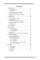
Contents 1 Introduction .................................................... 4 1.1 1.2 1.3 1.4 1.5 Package Contents ........................................................... Specifications ................................................................. Motherboard Layout (K7VT4-4X) .................................. Motherboard Layout (K7VT4-8X) .................................. ASRock I/OTM (K7VT4-4X / K7VT4-8X) .......................... 4 5 7 8 9 2 Installation ...................................
Chapter 1 Introduction Thank you for purchasing ASRock K7VT4-4X / K7VT4-8X motherboard, a reliable motherboard produced under ASRock’s consistently stringent quality control. It delivers excellent performance with robust design conforming to ASRock’s commitment to quality and endurance. Chapter 1 and 2 of this manual contain introduction of the motherboard and step-bystep installation guide for new DIY system builders. Chapter 3 and 4 contain basic BIOS setup and support CD information.
1.2 Specifications Platform: CPU: ATX form factor (12.0" x 7.0", 30.5 x 17.8 cm) Supports Socket A (462 pins) for AMD AthlonTM / AthlonTM XP / DuronTM processor Chipsets: North Bridge (K7VT4-4X): VIA KT400/4X (VT8367), FSB@333 MHz, AGP 4X; North Bridge (K7VT4-8X): VIA KT400/8X (VT8377), FSB@333 MHz, AGP 8X/4X South Bridge: VIA VT8235CD, supports USB 2.0, ATA 133 Clock Generator: 100 MHz - 200MHz Memory: 2 DDR DIMM Slots: DDR1 and DDR2 supports PC1600 / PC2100 / PC2700, Max.
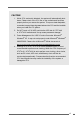
CAUTION! 1. While CPU overheat is detected, the system will automatically shutdown. Please check if the CPU fan on the motherboard functions properly before you resume the system. To improve heat dissipation, remember to spray thermal grease between the CPU and the heatsink when you install the PC system. 2. Do NOT insert a 3.3V AGP card into the AGP slot of K7VT4-4X or K7VT4-8X motherboard! It may cause permanent damage! 3. Power Management for USB 2.0 works fine under Microsoft® Windows® XP.
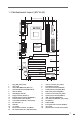
1.3 Motherboard Layout (K7VT4-4X) 2 1 3 5 4 6 17.8cm (7.0 in) 1 FID3 1 FID2 FID1 FID0 1 1 1 29 LAN USB01 USB23 GAME AUDIO1 AUDIO1 GAME 28 27 26 25 24 Line out 0 1 2 3 IDE2 VIA KT400/4X Chipset Line Line In in AUX1 Mic Mic in In IDE1 7 8 CD1 JR1 K7VT4-4X REV. 3.00 AUDIO1 JL1 1 9 AGP1 23 22 LAN PHY AUDIO CODEC PCI 1 FSB_SEL0 10 1 PCI 2 Super I/O 21 20 PCI 3 2MB BIOS 11 VIA VT8235 USB2.0 5.
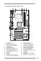
1.4 Motherboard Layout (K7VT4-8X) 2 1 3 5 4 6 17.8cm (7.0 in) 1 FID3 1 FID2 FID1 FID0 1 1 1 29 LAN USB01 USB23 GAME AUDIO1 AUDIO1 GAME 28 27 26 25 24 Line out 0 1 2 3 IDE2 VIA KT400/8X Chipset Line Line In in AUX1 Mic Mic in In IDE1 7 8 CD1 JR1 K7VT4-8X REV. 3.00 AUDIO1 JL1 1 9 AGP1 23 22 LAN PHY AUDIO CODEC PCI 1 FSB_SEL0 10 1 PCI 2 Super I/O 21 20 PCI 3 2MB BIOS 11 VIA VT8235 USB2.0 5.
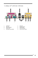
1.5 ASRock I/O TM (K7VT4-4X / K7VT4-8X) 1 10 1 3 5 7 9 9 Parallel port Game port Line In (Light Blue) USB 2.
Chapter 2 Installation K7VT4-4X / K7VT4-8X is an ATX form factor (12.0" x 7.0", 30.5 x 17.8 cm) motherboard. Before you install the motherboard, please study the configuration of your chassis to ensure that the motherboard fits into it. Make sure to unplug the power cord before installing or removing the motherboard. Failure to do so may cause physical injuries to you and damages to motherboard components. 2.
2.3 CPU Installation Step 1. Step 2. Step 3. o Unlock the socket by lifting the lever up to a 90 angle. Position the CPU directly above the socket such that its marked corner matches the base of the socket lever. Carefully insert the CPU into the socket until it fits in place. The CPU fits only in one correct orientation. DO NOT force the CPU into the socket to avoid bending of the pins. Step 4.
2.5 Installation of Memory Modules (DIMM) K7VT4-4X / K7VT4-8X motherboard provides two 184-pin DDR (Double Data Rate) DIMM slots. Please make sure to disconnect power supply before adding or removing DIMMs or the system components. Step 1. Step 2. Step 3. Unlock a DIMM slot by pressing the retaining clips outward. Align a DIMM on the slot such that the notch on the DIMM matches the break on the slot.
2.7 Jumpers Setup The illustration shows how jumpers are setup. When the jumper cap is placed on pins, the jumper is “SHORT”. If no jumper cap is placed on the pins, the jumper is “OPEN”. The illustration shows a 3-pin jumper whose pin1 and pin2 are “SHORT” when jumper cap is placed on these 2 pins. Jumper FSB_SEL0 (see p.7/p.
FID Jumpers (FID0, FID1, FID2, FID3, FID4) (see p.7/p.8 item 29) FID4 1 FID3 1 FID2 1 FID1 1 FID0 1 Note: The set of FID jumpers are only for advanced users to adjust the multiplier of CPU. Please follow the table below to adjust the multiplier of CPU. However, the system will work well without the adjustment of multiplier. You do not have to adjust the multiplier for normal usage. Multiplier FID0 FID1 FID2 FID3 FID4 5x 5.5x 2-3 1-2 2-3 2-3 1-2 1-2 2-3 2-3 2-3 2-3 6x 6.
Clear CMOS CLRCMOS1 CLRCMOS2 (see p.7/p.8 item 19) (see p.7/p.8 item 18) solder points 2-pin jumper Note: CLRCMOS1 and CLRCMOS2 allow you to clear the data in CMOS. The data in CMOS includes system setup information such as system password, date, time, and system setup parameters. There are 2 ways for you to clear and reset the system parameters to the default setup.
2.8 Connectors Connectors are NOT jumpers. DO NOT place jumper caps over these connectors. Connector Figure Description FDD connector (33-pin FLOPPY1) Red marking FLOPPY1 Pin1 (see p.7/p.8 item 13) Note: Match the red marking on the floppy ribbon cable with Pin1. Primary IDE connector (Blue) (39-pin IDE1, see p.7/p.8 item 8) PIN1 Secondary IDE connector (Black) (39-pin IDE2, see p.7/p.
Front panel audio connector (9-pin AUDIO1) (see p.7/p.8 item 24) GND +5VA BACKOUT-R BACKOUT-L 1 AUD-OUT-L DUMMY AUD-OUT-R MIC-POWER MIC System panel connector (9-pin PANEL1) (see p.7/p.8 item 14) PLED+ PLEDPWRBTN# GND 1 This is an interface for the front panel audio cable that allows convenient connection and control of audio devices. This connector accommodates several system front panel functions. DUMMY RESET# GND HDLEDHDLED+ External speaker connector (4-pin SPEAKER 1) (see p.7/p.
Chapter 3 BIOS Setup 3.1 BIOS Setup Utility This section explains how to use the BIOS Setup Utility to configure your system. The Flash Memory on the motherboard stores the BIOS Setup Utility. You may run the BIOS Setup when you start up the computer. Please press during the PowerOn-Self-Test (POST) to enter the BIOS Setup Utility, otherwise, POST will continue with its test routines.
Navigation Key(s) / / + / Function Description Displays the General Help Screen Jumps to the Exit menu or returns to the upper menu from the current menu Moves cursor up or down between fields Selects menu to the left or right Increases or decreases values Brings up a selected menu for a highlighted field Loads all the setup items to default value Saves changes and exits Setup 3.2 Main Menu When you enter the BIOS Setup Utility, the following screen appears.
TYPE To set the type of the IDE device, first, please select “IDE Devices” on Main menu and press to get into the sub-menu. Then, select among “Primary IDE Master”, “Primary IDE Slave”, “Secondary IDE Master”, and “Secondary IDE Slave” to make configuration of its type. Below are the configuration options. AMIBIOS SETUP UTILITY - VERSION 3.
[CD/DVD]: This is used for IDE CD/DVD drives. [ARMD]: This is used for IDE ARMD (ATAPI Removable Media Device), such as MO. Cylinders This is used to configure the number of cylinders. Refer to the drive documentation to determine the correct value. Heads This is used to configure the number of read/write heads. Refer to the drive documentation to determine the correct values. Write Pre-compensation Enter Write Pre-compensation sector. Refer to the drive documentation to determine the correct value.
Chapter 4 Software Support 4.1 Install Operating System This motherboard supports various Microsoft® Windows® operating systems: 98 SE / ME / 2000 / XP. Because motherboard settings and hardware options vary, use the setup procedures in this chapter for general reference only. Refer to your OS documentation for more information. 4.2 Support CD Information The Support CD that came with the motherboard contains necessary drivers and useful utilities that will enhance the motherboard features. 4.2.
Appendix: Advanced BIOS Setup This section will introduce you the following BIOS Setup menus: “Advanced,” “Security,” “Power,” “Boot,” and “Exit.” 1. Advanced BIOS Setup Menu Main Advanced AMIBIOS SETUP UTILITY - VERSION 3.31a Boot Power Exit Security [ Spread Spectrum CPU Host Frequency Actual Frequency DRAM Frequency Disabled Auto 133MHz Auto Setup Help ] to enable or disable the feature of spread spectrum.
Chipset Configuration: AMIBIOS SETUP UTILITY - VERSION 3.31a Advanced Chipset Configuration [ Setup Help ] AGP Mode AGP Aperture Size AGP Fast Write PCI Delay Transaction Auto 64MB Disabled Disabled USB Controller USB Device Legacy Support Disabled Disabled DRAM CAS# Latency Auto Over Vcore Voltage Disabled F1:Help Esc:Previous Menu :Select Item +/-:Change Values Enter:Select Sub-Menu to select [4X], [2X], [1X] as the AGP mode.
Resource Configuration: AMIBIOS SETUP UTILITY - VERSION 3.31a Advanced Resource Configuration PCI Latency Timer (PCI Clocks) Primary Graphics Adapter F1:Help Esc:Previous Menu :Select Item [ Setup Help ] 32 PCI +/-:Change Values Enter:Select Sub-Menu to select PCI clocks. Leave on default setting for the best PCI performance. F9:Setup Defaults F10:Save & Exit PCI Latency Timer (PCI Clocks): The default is 32.
OnBoard FDC: Use this to enable or disable floppy drive controller. OnBoard Serial Port: Use this to set addresses for the onboard serial ports or disable serial ports. Configuration options: [Auto], [Disabled], [3F8 / IRQ4 / COM1], [2F8 / IRQ3 / COM2], [3E8 / IRQ4 / COM3], [2E8 / IRQ3 / COM4]. OnBoard Infrared Port: You may select [Auto] or [Disabled] for this onboard infrared port feature. OnBoard Parallel Port: Select Parallel Port address or disable Parallel Port.
2. Security Setup Menu Main AMIBIOS SETUP UTILITY - VERSION 3.31a Boot Power Exit Security Advanced [ Setup Help ] Supervisor Password User Password Clear Clear Set Supervisor Password Set User Password [ Enter ] [ Enter ] Password Check Setup F1:Help Esc:Exit :Select Item :Select Menu to set the supervisor password. +/-:Change Values Enter:Select Sub-Menu F9:Setup Defaults F10:Save & Exit Supervisor Password: This field shows the status of the Supervisor Password.
3. Power Setup Menu Main Advanced AMIBIOS SETUP UTILITY - VERSION 3.
4. Boot Setup Menu Main AMIBIOS SETUP UTILITY - VERSION 3.31a Boot Power Exit Security Advanced [ Quick Boot Mode Boot Up Num-Lock Boot To OS/2 Boot From Network Disabled On No Disabled Setup Help ] to enable or disable the quick boot mode. Boot Device Priority F1:Help Esc:Exit :Select Item :Select Menu +/-:Change Values Enter:Select Sub-Menu F9:Setup Defaults F10:Save & Exit Quick Boot Mode: Enable this mode will speed up the boot-up routine by skipping memory retestings.
5. Exit Menu Main Advanced AMIBIOS SETUP UTILITY - VERSION 3.31a Boot Power Exit Security Exit Saving Changes Exit Discarding Changes Load Default Settings Discard Changes F1:Help Esc:Exit [ [ [ [ Enter Enter Enter Enter :Select Item :Select Menu [ Setup Help ] ] ] ] ] Exits and saves the changes in CMOS RAM. +/-:Change Values Enter:Select Sub-Menu F9:Setup Defaults F10:Save & Exit Exit Saving Changes: After you enter the sub-menu, the message “Save current settings and exit” will appear.