
Installation Guide

Page 4L123 0808A
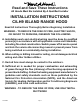
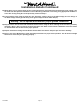
Centerline
of Hood
Centerline
of Hood
Vent Holes
Electrical (2)
11” 11”
7 ¼”
8” Transition
Opening (2)
3” Below To p
of Hood
5” x 16”
Exhaust
Opening (s)
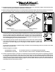
9"
16"5"
8" Round 8" Round
9"
16"5"
8" Round 8" Round
9"
9"
9"
9"
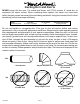
Brass Screws
A
Blower Wheel
B
Blower Housing
Installation Details Continued
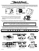
8) Turn the hood over on the protective surface. Attach the transition to each dual blower assembly and seal with duct
tape. The transition must t inside the exhaust collar on the blower assembly.
7) Remove the three screws retaining the blower motors. Unplug
and remove the motors, taking care not to damage the blower
wheels. It is not necessary to remove the blower wheels from
the motors.
Connection Diagram (42”- 54” Widths)
550 CFM T200 Dual Blower
(Top View)
VP565 Transition
(Included)
Transition Installed
(Side View)
Connection Diagram (60”- 66” Widths)
1100 CFM T2+200 Dual Blower
(Top View)
VP565 Transition
(Two included)
Transitions Installed
(Side View)
Warning: Make sure power is off and locked at the service disconnecting
means on the service panel during installation.
9) Install an appropriate 1/2” UL listed electrical wire clamp through each motor box electrical opening on the top of the
hood. Install electrical wiring from the service panel to the hood location for each motor box. Consult the connection
diagrams (below) for further details on electrical placement. Support the hood beneath the location where it will hand
and feed the electrical wire(s) through the wire clamp(s). Tighten the wire clamp(s).
Model Volts Amps* Hz RPM
CFM
SP@0.0"
Equivalent CFM
•
CFM
SP@0.1"
CFM
SP@0.2"
CFM
SP@0.3"
Minimum Round
Duct Size
Sones
#
T200 Island Dual 115 2.9 60 1550 550 900 507 471 431 8" (50 in.
2
) 6.0
* Add 0.5 amp for each halogen light.
• BecausetheMagicLung
®
blowerusescentrifugalltrationratherthanconventionalbafeormeshlters,theMagicLung
®
blowercanhandlecookingequipmentwithhighercubicfeetperminute(CFM)requirementsandcandeliverequivalentCFMmuchmore
efcientlythanotherthanotherltrationsystems.WhencomparingtheMagicLung
®
withotherblowerunitsmadebyothermanufacturers,usethe“EquivalentCFM”.
#
RatingsinaccordancewiththeStandardTestCodebytheEnergySystemsLaboratoryoftheTexasEngineeringExperimentStation.
6) Remove the blower shields (A) by loosening the two brass screws on the bottom of the shield. Gently close the back
draft dampers from the top side of the hood. To remove the blower housings, unsnap the suitcase latches (B) (one on
each side of the housing). The housings should be pulled forward and gently “tipped” to clear the blower wheels and
then out of the hood. Place the hood upside-down on the protective surface.