SM
CAUTION Follow the Installation Instructions before proceeding. Set the thermostat mode to “OFF” prior to changing settings in setup or restoring Factory Defaults. FCC Compliance Statement This equipment has been tested and found to comply with the limits for an intentional radiator, pursuant to Part 15, subpart C of the FCC rules. These limits are designed to provide reasonable protection against harmful interference in a residential installation.
Under Industry Canada regulations, this radio transmitter may only operate using an antenna of a type and maximum (or lesser) gain approved for the transmitter by Industry Canada. To reduce potential radio interference to other users, the antenna type and its gain should be so chosen that the equivalent isotropically radiated power (e.i.r.p.) is not more than that necessary for successful communication. Cet appareil est conforme avec Industrie Canada, exempts de licence standard RSS(s).
Glossary of Terms Auto-Changeover: A mode in which the thermostat will turn on the heating or cooling based on room temperature demand. Cool Setpoint: The warmest temperature that the space should rise to before cooling is turned on (without regard to deadband). Deadband: The number of degrees the thermostat will wait, once a setpoint has been reached, before energizing heating or cooling. Differential: The forced temperature difference between the heat setpoint and the cool setpoint.
Table Table of of Contents Contents GET TO KNOW YOUR THERMOSTAT Get to Know Your Thermostat........................................................ 1 Quick Start...................................................................................... 6 INTALLATION INSTRUCTIONS Installation Instructions.................................................................. 9 Sample Wiring Diagrams............................................................... 13 Test Operation........................................
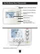
Get To Know Your Thermostat Optional Wireless Module Backlit, Scrolling Display Backlit Cooler & Warmer Buttons Backlit LCD Display Mode Button Heat or Cool Demand Indicator Red = Heat, Green = Cool Setup Buttons Behind Door 1
Get To Know Your Thermostat Setup Buttons 2
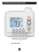
Get To Know Your Thermostat Display Features 4 1 2 Pm 18:88Am 2nd3rd Program ONOFF Stage 188 188 C L HI OO Setup Step Day Night Morning Evening 6 Fan On Outdoor 188 3 AUXHEAT 88 3 Lo 5 1 The scrolling display will be used to help you easily navigate the setup screens in the thermostat. 2 Clock with Day of the Week Indicates the current time and day. This clock is also used to program the time period schedules. 3 Mode Indicators Selects the operational mode of the equipment.
Get To Know Your Thermostat Display Features 11 Pm 18:88Am 10 8 188 C L 2nd3rd Program ONOFF Stage 188 HI OO Setup Step Day Night Morning Evening Fan On Outdoor 188 AUXHEAT 88 Lo 7 12 9 7 7 Desired Set Temperature Indicates desired room temperature(s). Also displays the highest and lowest temperatures for the day. 8 Morning, Day, Evening & Night icons Indicates the day part of the time period program.
Get to know your thermostat Display Features Pm 18:88Am 2nd3rd Program ONOFF Stage 188 188 C L HI OO 15 Setup Step 16 Day Night Morning Evening Fan On Outdoor 188 13 AUXHEAT 88 Lo 14 13 AuxHeat icon Indicates 2nd stage electric strip heat is being used when the thermostat is programmed for Heat Pump operation. Only the Aux icon will appear during Cool to Dehumidify to indicate Reheat operation. 14 Lo icon Indicates the lowest recorded outdoor temperature for the day.
Quick Start During Setup and Programming Press the WARMER or COOLER buttons to modify the selection. Press the MODE button to advance and confirm through the setup steps. Setting the Clock and Day* *Not available when connected to a Skyport Account Press the SET CLOCK button. Adjust the clock using the WARMER or COOLER buttons. Press MODE to advance to the day setting. Adjust the day using the WARMER or COOLER buttons. Press the SET CLOCK button to confirm settings.
Quick Start Selecting your desired temperature AUTO-CHANGEOVER MODE - Pressing the WARMER or COOLER buttons in Auto mode will adjust both the heat and cool setpoints simultaneously. To adjust heat and cool setpoints individually, choose HEAT mode to adjust the heat setpoint and COOL mode to adjust the cool setpoint, then return to AUTO mode. HEAT OR COOL MODE - Pressing the WARMER or COOLER buttons in Heat or Cool mode will adjust only the heat or cool setpoints individually displayed.
Installation Instructions Remove and Replace the old thermostat To install the thermostat properly, please follow these step by step instructions. If you are unsure about any of these steps, call a qualified technician for assistance. • Assemble tools: Flat blade screwdriver, wire cutters and wire strippers. • Make sure your Heater/Air Conditioner is working properly before beginning installation of the thermostat. • Carefully unpack the thermostat. Save the screws, any brackets, and instructions.
Installation Instructions Wire Connections If the terminal designations on your old thermostat do not match those on the new thermostat, refer to the chart below or the wiring diagrams that follow. Wire from the old thermostat Function terminal marked Install on the new thermostat connector marked G or F Fan G Y1, Y Cooling Y1 W1, W Heating W1/0/B Rh, R, M, Vr, A Power R C Common C O/B Rev.
Installation Instructions The Voyager Thermostat Backplate R G W1/O/B W2 Y1 Y2 W3 R G W1/O/B W2 Y1 Y2 W3 To remove the thermostat backplate: Gently separate the display from the base by pulling first from one side, then the other until the two pieces unsnap. A small screwdriver may be used, very carefully, to start seperating the two pieces.
Installation Instructions Check Dip Switch Ensure which switch is correct for your system. Dip switches are located on the back of the thermostat. ELEC 2 B 3 3 GAS 1 1 HP 3 3 ELEC 1. When GAS/EL or HP is set for GAS/EL: This switch (GAS or ELEC) controls how the thermostat will control the Fan (G) terminal in heating mode. When GAS is chosen, the thermostat will not energize the Fan (G) terminal in heating. When ELEC is chosen the thermostat will energize the fan in heating.
Installation Instructions Sample Wiring Diagrams Conventional Heating and Cooling Systems 3 Wire, Heat Only 4 Wire, Cool Only Residential & Commercial 1 Stage Heating with no Fan. Residential & Commercial 1 Stage Cooling.
Installation Instructions Sample Wiring Diagrams Heat Pump Systems 5 Wire, 1 Stage Cooling, 1 Stage Heat 6 Wire, 1 Stage Cooling, 2 Stage Heat Residential & Commercial Heat Pump with ‘O’ Reversing Valve R C W1/O/B Y1 G J1 J2 J3 = = = 24VAC Power 24VAC Common Reversing Valve 1st Stage Compressor (Cool or Heat) Fan Heat Pump O Gas Residential & Commercial Heat Pump with ‘O’ Reversing Valve R C W1/O/B Y1 W2 G J1 J2 J3 = = = 24VAC Power 24VAC Common Reversing Valve 1st Stage Compressor (Cool or Heat) A
Installation Instructions Sample Wiring Diagrams Dry Contact R G W1/O/B W2 Y1 Y2 W3 C OUTDOOR SENSOR REMOTE SENSOR DRY CONTACT 11 12 1 2 10 9 3 4 8 7 6 5 Accessory such as a Time Clock or door switch 14
Installation Instructions Test Operation The technician setup is a diagnostic feature that enables testing of all outputs. To enter Technician Setup, press and hold the SETUP button for 5 seconds until all the icons appear. Follow the next steps to view settings and test equipment. 1. Press MODE to view the version numbers of the thermostat. 2. Press MODE again to view the jumper settings and current state of the Dry Contact terminals. 3.
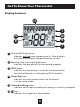
User Setup: Backlight Operation How to Change Settings in the Setup Screens To enter Advanced Setup, press the SETUP button, then press MODE. Use the WARMER or COOLER buttons to adjust the value of your selection. Press MODE to advance to the next setup step. Press SETUP again to leave the setup screens. WARMER Setup MODE COOLER Backlight (setup step 3-8) Backlight (setup step 3) Off - Backlight turns on with any button press and turns off after 8 seconds. On - Backlight is on continuously.
User Setup: Scrolling Screen and Display Options Scrolling Display Method (Setup Step 16) This option allows the user to choose how the scrolling text is displayed. Options are: Scrolling Scroll Letters Slow Scroll Letters Fast Scroll Words Slow Scroll Words Fast Non-Scrolling Whole Words Slow Whole Words Fast Words Centered Slow Words Centered Fast 1 Press the SETUP button, then press MODE repeatedly until the Scrolling Method setup step appears. Use the WARMER or COOLER buttons to make selection.
User Setup Vacation & Away Settings The Vacation feature allows the thermostat to use temporary, VACATION energy saving setpoints without having to change regular programming. The HOME/AWAY feature allows for a one button press to bring in your stored unoccupied vacation settings. A subsequent press of the HOME/AWAY button restores the last used comfort settings. HOME/ AWAY Press the VACATION button to enter Vacation/Away programming.
User Setup - Wireless Modules Wireless Module Wireless Module ACCESSORY STATUS ACCESSORY SETUP The Accessory Status button allows the user to view the status of wired and wireless accessories. For many of the wireless devices this status includes: Battery Level, Signal Strength & Last Time Updated. If there is an optional wireless module installed, the Accessory Setup button allows the user to link or connect wireless devices to the thermostat, or the thermostat to the network.
User Setup - Wireless Modules Wi-Fi Module Wi-Fi Module ACCESSORY STATUS ACCESSORY SETUP Please follow the instructions included with the Wi-Fi module to connect to an Access Point or view status. The general instructions are below. Wi-Fi Module If the is present on the display then the thermosat is connected to the Wi-Fi Access Point. If just the “dot” of this icon appears, then just the Wi-Fi module is recognized.
User Setup - Wireless Modules Z-Wave Module Z-Wave Module ACCESSORY STATUS ACCESSORY SETUP Please follow the instructions included with the Z-Wave module to join the Network or view status. The general instructions are below. Z-Wave Module Press the Accessory Status button to view the status of the thermostat’s connection to the Network.
User Setup - Wireless Modules ZigBee Module ZigBee Module ACCESSORY STATUS ACCESSORY SETUP Please follow the instructions included with the ZigBee module to join the Network or view status. The general instructions are below. ZigBee Module Press the Accessory Status button to view the status of the thermostat’s connection to the Network.
User Setup - Service Filter These setup steps allow the user to monitor equipment runtimes and program service alerts. Service alerts are displayed in the scrolling marquee. Runtime hours or days appear in the clock display. FAN ON OUTDOOR˚ AUTO 30 Setup Step Press and hold FAN to clear service alert messages from the scrolling marquee.
User Setup - Runtimes To view, set, or reset System Runtimes, press the SETUP button, then press MODE. Press MODE to advance to the desired setup step. Use the WARMER or COOLER buttons to adjust the value of your selection. Press SETUP again to leave the setup screens. UV Lamp Runtime (setup steps 11, 14) Current UV Lamp Calendar Days (Setup Step 11) - This counter displays the total number of calendar days that have elapsed to help the user track UV lamp runtime. Press FAN to reset.
User Setup - Time Period Programming Selecting Your Time Period Schedule (setup step 1) This thermostat may be configured to be programmable or non programmable. 7 Day Program - Allows all seven days to be programmed independently. Non Program - No advanced time period programming available. 1 Day Program - Allows one 24 hour day to be programmed. This same schedule will be repeated every day the program is set to run. 5/2 Day Program - Allows weekdays, Saturday, and Sunday to be programmed independently.
User Setup - Time Period Programming This thermostat features four programmable time periods per 24 hour day: Morning, Day, Evening, and Night. The start time for each time period is adjustable. The stop time for each time period is the start time for the next period. Each time period, or day part may be individually disabled. Select the Day to Program - Press the WARMER or COOLER to select the desired Day or Week Part in the case of 5-2 (weekday – weekend) programming.
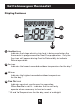
Installer Setup How to Change Settings in the Setup Screens To enter Advanced Setup, press the SETUP button, then press MODE. Use the WARMER or COOLER buttons to adjust the value of your selection. Press MODE to advance to the next setup step. Press SETUP again to leave the setup screens. WARMER SETUP MODE COOLER Selecting Your Time Period Schedule (setup step 1) This thermostat may be configured to be programmable or non programmable.
Installer Setup Setpoint Limits (setup step 17) When this feature is set to USE, the heat and cool setpoints can be restricted to preset levels, set in steps 18 and 19. Maximum Heat Setpoint (Setup Step 18) - (35˚ - 99˚). Minimum Cool Setpoint (Setup Step 19) - (35˚ - 99˚). Cycles Per Hour (setup step 20) The Cycles Per Hour setting may limit the number of times per hour your HVAC unit may energize.
Installer Setup Deadband Settings (setup steps 27 - 36) The Deadband is the number of degrees or minutes that the thermostat waits before it initiates the stages of heating or cooling. 1st Stage Deadband (Setup Step 27) - Specifies the minimum temperature difference between the room temperature and the desired setpoint before the first stage of heating or cooling is allowed to turn on.
Installer Setup Programming the Fan (setup steps 37 - 40) (This feature not available on all models) Fan Program (Setup Step 37) - This feature allows the fan to be programmed to turn on automatically for a specified amount of time during the day. If this feature is set to ON, the next three steps will appear. Minutes of Fan Runtime Per Hour (Setup Step 38) - This setting specifies the number of minutes (0 - 60, in increments of 5) that the fan will run at the top of each hour.
Installer Setup Control to Temp Source (setup step 42) This feature allows the user to specify which temperature sensor source the thermostat will use to measure room temperature. Thermostat: Uses the internal thermostat sensor only. Remote Sensor: Uses wireless or wired sensors only. Fahrenheit or Celsius (setup step 44) This feature allows the thermostat to display temperature in Fahrenheit or Celsius.
Installer Setup Dry Contact Operation (Setup Step 46) Dry Contact Polarity ‘Active’ ‘Idle’ Dry Contact Closed (Normally Closed) - The dry contact is closed until the connected device opens the circuit. Dry Contact ‘Idle’ Dry Contact Dry Contact Open (Normally Open) - The dry contact is open until the connected device closes the circuit.
Installer Setup Resetting the Thermostat to the Factory Default Settings (for default values see page 36, Advanced SetupTable) If, for any reason, you desire to return all the stored settings back to the factory default settings, follow the instructions below. WARNING: This will reset all Time Period and Advanced Programming to the default settings. Any information entered prior to this reset may be permanently lost.
Installer Setup Locking/Unlocking the Keypad To prevent unauthorized use of the thermostat, the front panel buttons may be disabled. To disable, or ‘lock’ the keypad, press and hold the MODE button. While holding the MODE button, press the WARMER and COOLER buttons icon will appear on the display, then release the buttons. together. The Press all three buttons in the order outlined above for keypad lockout WARMER COOLER MODE To unlock the keypad, press and hold the MODE button.
Technician Setup To enter Technician Setup, press and hold the SETUP button for 10 seconds. After all the icons appear, press MODE. The version number of the thermostat will appear in the scrolling text. Press MODE to advance to the next step. Use the WARMER or COOLER buttons to adjust the value of your selection. To leave Technician Setup, press SETUP.
e e n n d .
Advanced Setup Table Df = Factory Default Setting Step# Description 33 34 35 36 37 38 39 40 41 42 43 44 45 46 47 48 49 50 Minutes Between 3rd and 4th Stage 2nd StageTurnoff Point 3rd StageTurnoff Point 4th Stage Turnoff Point Fan Program Minutes of Fan Runtime Fan Program Start Time Fan Program Stop Time Wired Sensor Type Control to Temp Source Fan Off Delay F/C Comfort Recovery Dry Contact Polarity Dry Contact Use Skyport Local API Press Fan To Clear All Messages Pg# Range Df 29 0 - 60 Minutes 29 Deadb
Troubleshooting • SYMPTOM: The air conditioning does not attempt to turn on. CAUSE: The compressor timer lockout may prevent the air conditioner from turning on for a period of time. REMEDY: Consult the Owner’s Manual in the Installer Setup section to defeat the Cycles Per Hour (page 29). • SYMPTOM: The display is blank. CAUSE: Lack of proper power. REMEDY: Make sure the power is on to the furnace and that you have 24vac between R & C. • SYMPTOM: The air conditioning does not attempt to turn on.
Index A Alerts see Runtime Accessory, 20 Setup, 20 Auto adjust temperature, 6 changeover, 3 fan, 7 mode, iii, 3, 7 B b reversing valve, 10, 44 Backplate, 11 Balance Point, 34 Buttons accessory, 2 cooler (down) 1 emergency heat, 2, 19 fan, 1, 2, 7 front panel, 1, 2 mode, 1, 6 outdoor, 1, 8 program, 1, 26 set clock, 2, 6 setup, 17 vacation, 2, 19 up (warmer), 1, 7 C Condensate Drain Pan, 37 Copy Function see Program C, 34 Cycles Per Hour, 29 Calibration, 16, 40 Celsius, 34 Clock display, 3 setting, 6
Index E Electric Heating AuxHeat icon, 5 jumper setting, 12 reheat, 32 Emergency Heat, 2, 19 F Factory Defaults settings, 41, 42, 43 resetting, 38 Fahrenheit, 34 Fan button function, see Buttons on during heat, see Electric Heat on icon, 5 program, see Programmable Fan runtime, 24 2nd stage heat, see Emergency Heat G Gas/Electric Furnace jumper, 12 Green Cool Indicator, 1 Heat 1st stage deadband, see Deadband min.
Index L LCD, 3, 4, 5 Language, 17 Locked Indication, see Keypad Lockout M Manual changeover, 6 cool, 6, 7 heat, 6, 7 Mode, 3, 6, 7, 28 Multi-stage Operation, 29, 30 N O O Reversing Valve see Reversing Valve Off Mode, 3, 6 Outdoor button, see Buttons viewing temperature, 8 Overcool, 32 P Pan, Service see Dry Contact Polarity, see Dry Contact Program Copy, 27 daily schedule, 26, 27 mode, 28 worksheet, back page Programmable Fan, 31 Non-Programmable Thermostat, 28 Programmable Thermostat, 26 Nor
Index S Schedule Daily, see Program 2nd stage turn off temperature, 30 Sensor outdoor, see Outdoor remote, see Remote thermostat, see Thermostat Service filter icon, see Reset pan icon, see Dry Contact UV light, see Reset Set Clock, see Clock Setpoint cool, see Cool Limits, 29 T Technician Setup, 16, 40 Thermostat Sensor calibrate, 16, 40 Three Stage Heat, 14, 30 Time, see Clock Time Delay, compressor lockout, 29 cycles per hour, 29 1st to 2nd stage, 30 2nd to 3rd stage, 30 3rd to 4th stage, 30 Time
Warranty One-Year Warranty - This Product is warranted to be free from defects in material and workmanship.
Programming Worksheet - see page 23 START TIME COOL HEAT Copy Mon to Tues No Yes Morning Day Evening Night Copy Tues to Wed No Yes Morning Day Evening Night Copy Wed to Thurs No Yes FRIDAY Morning Day Evening Night Copy Thurs to Fri No Yes SATURDAY Morning Day Evening Night Copy Fri to Sat No Yes Morning Day Evening Night Copy Sat to Sun No Yes THURSDAY WEDNESDAY TUESDAY Morning Day Evening Night SUNDAY MONDAY DAY PERIOD Morning Day Evening Night
Patent Pending Printed on recycled paper. P/N 88-1016 Rev.