
Data Sheet
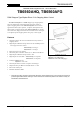
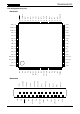


TB6560AHQ/AFG
2014-10-01
9
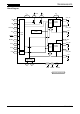
Functional Descriptions
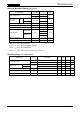
1. Excitation Mode Settings
The excitation mode can be selected from the following four modes using the M1 and M2 inputs. (The
2-phase excitation mode is selected by default since both M1 and M2 have internal pull-down resistors.)
Inputs
Mode
(Excitation)
M2 M1
L L 2-phase
L H 1-2-phase
H L 4W1-2-phase
H H 2W1-2-phase
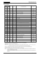
2. Function Table (Relationship Between Inputs and Output Modes)
When the ENABLE pin is Low, outputs are off. When the
RESET
pin is Low, the outputs are put in the
Initial mode as shown in the table below. In this mode, the states of the CLK and CW/CCW pins are
don’t-cares.
Inputs
Output Mode
CLK CW/CCW
RESET
ENABLE
L H H CW
H H H CCW
X X L H Initial mode
X X X L Z
X: Don’t care
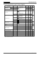
3. Initial Mode
When
RESET
is asserted, phase currents in each excitation mode are as follows. At this time, the M
O
pin
goes Low (open-drain connection).
Excitation Mode A-Phase Current B-Phase Current
2-phase 100 % −100 %
1-2-phase 100 % 0 %
2W1-2-phase 100 % 0 %
4W1-2-phase 100 % 0 %
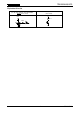
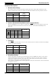
4. Decay Mode Settings
It takes approximately four OSC cycles for discharging a current in PWM mode. The 25 % decay mode is
created by inducing decay during the last cycle in Fast Decay mode; the 50 % Decay mode is created by
inducing decay during the last two cycles in Fast Decay mode; and the 100 % Decay mode is created by
inducing decay during all four cycles in Fast Decay mode.
Since the DCY1 and DCY2 pins have internal pull-down resistors, the Normal mode is selected when DCY1
and DCY2 are undriven.
DCY2 DCY1 Current Decay Setting
L L Normal 0 %
L H 25 % Decay
H L 50 % Decay
H H 100 % Decay