
Data Sheet
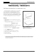


TB6560AHQ/AFG
2014-10-01
3
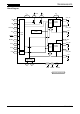
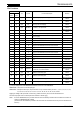
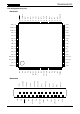
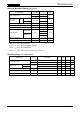
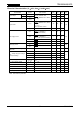
Pin Functions
Pin No.
I/O Symbol Functional Description Remarks
TB6560
AHQ
TB6560
AFG
1 42 Input TQ2 Torque setting input (current setting)
Internal pull-down
resistor
2 43 Input TQ1 Torque setting input (current setting)
Internal pull-down
resistor
3 45 Input CLK Clock input for microstepping
Internal pull-down
resistor
4 47 Input ENABLE H: Enable; L: All outputs OFF
Internal pull-down
resistor
5 48 Input
RESET
L: Reset (The outputs are reset to their initial states.)
Internal pull-down
resistor
6 50/51 SGND Signal ground (for control block) (Note 1)
7 53 OSC
A CR oscillation circuit is connected to this pin. Performs
output chopping.
8 55/56 Input VM
B
Motor power supply pin (for phase-B driver) (Note 1)
9 61/62 Output OUT_BM OUT_B output (Note 1)
10 64 (*) PGNDB Power ground
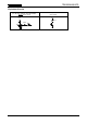
11 2/4 (*) N
FB
Connection pin for a B-channel current sensing resistor
Two pins of the TB6560AFG should be short-circuited.
(Note 1)
12 6/7 Output OUT_BP OUT_B output
(Note 1)
13 10/11 Output OUT_AM OUT_A output
(Note 1)
14 13/14 (*) N
FA
Connection pin for an A-channel current sensing resistor
Two pins of the TB6560AFG should be short-circuited.
(Note 1)
15 16 PGNDA Power ground
16 19/20 Output OUT_AP OUT_A output (Note 1)
17 23 Output M
O
Initial state sensing output. This pin is enabled in the initial
state.
Open drain
18 25/26 Input VM
A
Motor power supply pin (for phase-A driver) (Note 1)
19 28 Output Protect When TSD is activated: High; when in normal state: High-Z. Open drain
20 30/31 Input V
DD
Power supply pin for control block (Note 1)
21 33 Input CW/CCW
Rotation direction select input.
L: Clockwise; H: Counterclockwise
Internal pull-down
resistor
22 35 Input M2 Excitation mode setting input
Internal pull-down
resistor
23 36 Input M1 Excitation mode setting input
Internal pull-down
resistor
24 38 Input DCY2 Current decay mode setting input
Internal pull-down
resistor
25 39 Input DCY1 Current decay mode setting input
Internal pull-down
resistor
(*): The pin assignment of the TB6560AFG is different from that of the TB6560FG.
TB6560AHQ: There is no no-connect (NC) pin.
TB6560AFG: Except the above pins, all pins are NC. The pin numbers of NC pins are: 1, 3, 5, 8, 9, 12, 15, 17, 18,
21, 22, 24, 27, 29, 32, 34, 37, 40, 41, 44, 46, 49, 52, 54, 57, 58, 59, 60, and 63.
Applying a voltage to NC pins does not cause any problem since they are not connected inside the IC.
All control input pins have an internal pull-down resistor of 100 kΩ (typ.)
Note 1: As for the TB6560AFG, two pins that have the same functionality should be short-circuited at a location as
close to the TB6560AFG as possible.
(The electrical characteristics provided in this document are measured when those pins are handled in this
manner.)