
Data Sheet


TB6560AHQ/AFG
2014-10-01
29
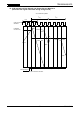
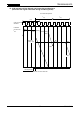
Application Circuit Example
Note: Capacitors for the power supply lines should be connected as close to the IC as possible.
Usage Considerations
• A large current might abruptly flow through the IC in case of a short-circuit across its outputs, a short-circuit
to power supply or a short-circuit to ground, leading to a damage of the IC. Also, the IC or peripheral parts
may be permanently damaged or emit smoke or fire resulting in injury especially if a power supply pin
(V
DD
, VM
A
, VM
B
) or an output pin (OUT_A P, OU T_AM, OUT_BP, O U T _BM) is short-circuited to adjacent
or any other pins. These possibilities should be fully considered in the design of the output, V
DD
, VM, and
ground lines.
• A fuse should be connected to the power supply line. The rated maximum current of the TB6560AHQ is
3.5 A/phase and that of the TB6560AFG is 2.5 A/phase. Considering those maximum ratings, an
appropriate fuse must be selected depending on operating conditions of a motor to be used. Toshiba
recommends that a fast-blow fuse be used.
• The power-on sequence described on page 28 must be properly followed.
• If a voltage outside the operating range specified on page 6 (4.5 ≤ V
DD
≤ 5.5, 4.5 ≤ VM
A/B
≤ 34,
V
DD
≤ VM
A/B
) is applied, the IC may not operate properly or the IC and peripheral parts may be
permanently damaged. Ensure that the voltage range does not exceed the upper and lower limits of the
specified range.
NFCompA
M
MCU
or
External
input
CLK
RESET
ENABLE
M1
M2
CW/CCW
DCY1
DCY2
TQ1
TQ2
Protect
M
O
R1
R2
OSC
100 pF
≈
400 kHz
SGND
PGND
Fuse
10
µ
F
5 V
1
µ
F
V
DD
VM
A
VM
B
1
µ
F
47
µ
F
24 V
Logic
Current
control
H-SW A
H-SW B
OUT_AP
OUT_AM
OUT_BP
OUT_BM
R
NFA
R
NFB
N
FA
N
FB
NFCompB
0.5
Ω
: I
OUT
(max)
=
1.0 A
PWM control
circuit
PWM control
circuit