
Data Sheet


TB6560AHQ/AFG
2014-10-01
20
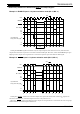
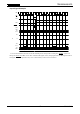
13. CLK and Internal OSC Signals and Output Current Waveform
(when the CLK signal is asserted during Slow Decay mode)
When the CLK signal is asserted, the Chopping Counter (OSC Counter) is forced to reset at the next rising
edge of the OSC signal.
As a result, the response to input data is faster compared to methods in which the counter is not reset.
The delay time that is theoretically determined by the logic circuit is one OSC cycle = 10 μs at a 100-kHz
chopping rate.
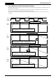
After the OSC Counter is reset by the CLK signal input, the current control mode is invariably switched to
Charge mode briefly for current sensing.
Note: Even in Fast Decay mode, the current control mode is invariably switched to Charge mode briefly for
current sensing.
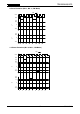
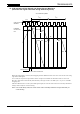
25 % Mixed Decay Mode
CLK Signal Input
Predefined
Curre
nt Level
I
OUT
RNF
Predefined
Current Level
f
chop
OSC Pin Internal
Waveform
Switches to Charge mode briefly
The OSC counter is reset here.
NF
RNF
MDT
NF
MDT
f
chop
f
chop