
Data Sheet


TB6560AHQ/AFG
2014-10-01
11
Relationship between the Enable and
and Output Signals
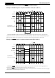
Example 1: ENABLE input in 1-2-phase excitation mode (M1: H, M2: L)
Setting the ENABLE signal Low disables only the output signals, while internal circuitry other than the
output block continues to operate in accordance with the CLK input. Therefore, when the ENABLE signal goes
High again, the output current generation is restarted as if phases proceeded with the CLK signal.
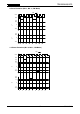
Example 2:
RESET
input in 1-2-phase excitation mode (M1: H, M2: L)
Setting the
RESET
signal Low causes the outputs to be put in the Initial state and the M
O
output to be
driven Low (Initial state: A-channel output current is at its peak (100 %)).
When the
RESET
signal goes High again, the output current generation is restarted at the next rising edge
of CLK with the state following the Initial state.
CLK
ENABLE
RESET
M
O
voltage
100
(%)
0
−
100
t
0
t
1
t
2
t
3
t
7
t
8
t
9
t
10
t
11
t
12
OFF
71
−
71
I
A
(current from
OUT_AP to OUT_AM)
CW
CLK
ENABLE
RESET
M
O
voltage
100
(%)
0
−100
t
0
t
1
t
2
t
3
t
7
t
8
t
4
t
5
t
2
t
3
71
−71
t
6
I
A
(current from
OUT_AP to OUT_AM)
CW
RESET