
Manual


Table Of Contents
- AMA2/AMA3
- HANDLEIDING
- MODE D'EMPLOI
- MANUAL
- ANLEITUNG
- SMS BERICHTEN VERZENDEN EN ONTVANGEN
- AMA2/3 REV 4.30
- AMA2/3 REV 4.30
- Fxxxxy=z
- AMA2/3 REV 4.30
- AMA2/3 REV 4.30
- AMA2/3 REV 4.30
- AMA2/3 REV 4.30
- AMA3: type van het alarmtoestel
- AMA2/3 REV 4.30
- AMA2/3 REV 4.30
- AMA2/3 REV 4.30 (De drukknopled brand continu bij het aanzetten van het contact)
- AMA3 REV 4.30
- OUTPUT OFF/ON
- 4. HOE WEET IK WANNEER IK GPS ONTVANGST (FIX) HEB?
- FR – MODE D’EMPLOI
- ENVOYER ET RECEVOIR DES MESSAGES SMS
- AMA2/3 REV 4.30
- AMA2/3 REV 4.30
- AMA2/3 REV 4.30
- AMA2/3 REV 4.30
- AMA2/3 REV 4.30
- AMA2/3 REV 4.30
- AMA3: type de système d’alarme.
- AMA2/3 REV 4.30
- AMA2/3 REV 4.30
- AMA3 REV 4.30
- AMA2/3 REV 4.30
- AMA2/3 REV 4.30
- AMA2/3 REV 4.30
- AMA2/3 REV 4.30
- AMA2/3 REV 4.30
- AMA2/3 REV 4.30
- AMA2/3 REV 4.30
- AMA2/3: device type
- AMA2/3 REV 4.30
- AMA2/3 REV 4.30 (service on = led on the push button blinks fast)
- or
- AMA2/3 REV 4.30 (service off = led on the push button burns continuously)
- AMA3 REV 4.30
- DE – ANLEITUNG
- 1. INSTALLATION
- Der AMA2/3 funktioniert mit einer SIM-Karte damit er eine SMS-Nachricht senden kann.
- AMA2/3 REV 4.30
- AMA2/3 REV 4.30
- AMA2/3 REV 4.30
- AMA2/3 REV 4.30
- AMA3: Typ Alarmgerät
- OUTPUT ON
- AMA2/3 REV 4.30
- OUTPUT OFF
- AMA2/3 REV 4.30
- SERVICE ON (die LED blind ständig beim Starten des Fahrzeuges)
- SERVICE OFF (die LED brennt beim Starten des Fahrzeuges)
- AMA3 REV 4.30
- OUTPUT OFF/ON
- AMA2/3 REV 4.30
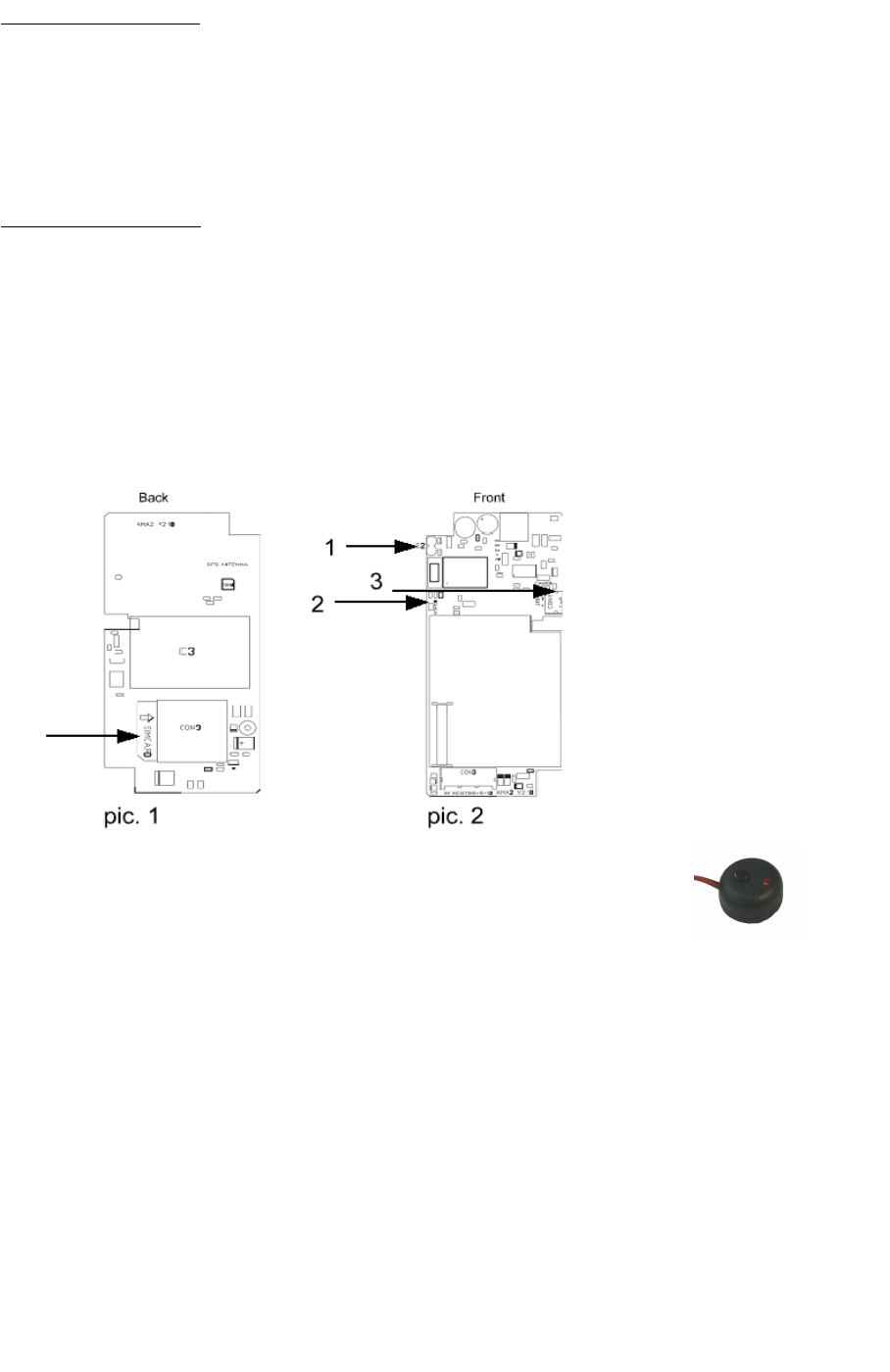
1. INSTALLATION
Attention! Only use a SIM-card with a removed password (to initialize through a GSM-cell
phone). Place the SIM-card into the right position (see pic. 1).
To activate the SIM-card = check if you can make a phone call with the SIM-card.
When removing the SIM-card from the AMA2/3, please ensure to remove the battery and the wiring
loom fuse first. After replacement of the SIM-card, you need to plug in the battery and the wiring loom
fuse again.
2 . CONNECTIONS
Red: + 12 Volt
Black: - Ground
Blue: + 15 (+ 12 V after ignition)
White: + 12 V OUT (output for buzzer or external apparatus, plug in via connector max 0,5 A)
Green: Auxilary input. Negative or Positive triggered according to the programming
Yellow: no application
Plug the buzzer into the connector.
Plug the push button (see pic. 3) into the connector.
Connect the red wire to the + 12 V (battery). pic. 3 push button
Connect the black wire to a good ground (battery).
Connect the blue wire to the + 12 V after ignition (+15V).
Plug in the internal battery after connecting the power supply. The AMA2/3 needs the battery
power to be able to connect to the GSM-network. The charge led (3 - pic.2) will burn when the back-
up battery is loading.
Attention: 1) The initial operation of the proposed procedure can last about 2 minutes to control
all the functions and connect to the GSM-network.
The status led (2 - pic. 2) on the PCB will blink every 5 seconds if the
AMA2/3 is connected to the network. If the status led blinks every second, it means
that no GSM-network connection has been made.
2) The AMA2/3 will indicate the signal strength through the buzzer and the external
push button led each time the ignition is switched off. Example: signal 3 = 3 x blinks
and 3 buzzer signals (0 buzzer signals = no signal, 5 buzzer signals = best signal)
21