
Data Sheet


VMA501
V. 01 – 29/03/2017 9 ©Velleman nv
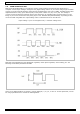
In this code, we are using the analogWrite (PWM interface, analogue value) function. We will read the analogue
value of the potentiometer and assign the value to PWM port, so there will be corresponding change to the
brightness of the LED. One final part will be displaying the analogue value on the screen. You can consider this
as the analogue value reading project adding the PWM analogue value assigning part.
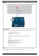
Result
After programming, rotate the potentiometer knob to see changes of the displaying value. Also, note the
obvious change of brightness on the breadboard.
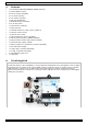
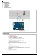
7.4 RGB LED Module
The RGB LED module is a full-colour LED allows for cool lighting effects.
Specifications
red Vf .............................................................................................................. 1.8 to 2.1 V
green Vf ........................................................................................................... 3.0 to 3.2 V
blue Vf ............................................................................................................. 3.0 to 3.2 V
red colour ........................................................................................................ 620-625 nm
green colour ..................................................................................................... 520-525 nm
blue colour ....................................................................................................... 465-470 nm
red brightness @ 20 mA ................................................................................... 600-800 mcd
green brightness @ 20 mA .............................................................................. 800-1000 mcd
blue brightness @ 20 mA .............................................................................. 1500-2000 mcd
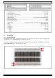
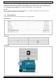
Pin Layout
Pin Name
Description
R
red
G
green
B
blue
-
GND
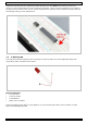
Connection