
Data Sheet


MFRC522 All information provided in this document is subject to legal disclaimers. © NXP Semiconductors N.V. 2016. All rights reserved.
Product data sheet
COMPANY PUBLIC
Rev. 3.9 — 27 April 2016
112139 79 of 95
NXP Semiconductors
MFRC522
Standard performance MIFARE and NTAG frontend
t
su(D-SCKH)
data input to SCK HIGH
set-up time
changing MOSI to
SCK
25 - - ns
t
h(SCKL-Q)
SCK LOW to data output
hold time
SCK to changing
MISO
- - 25 ns
t
(SCKL-NSSH)
SCK LOW to NSS HIGH
time
0- - ns
t
NHNL
NSS high before
communication
50 - - ns
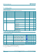
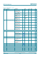
Table 155. I
2
C-bus timing in Fast mode
Symbol Parameter Conditions Fast mode High-speed
mode
Unit
Min Max Min Max
f
SCL
SCL clock frequency 0 400 0 3400 kHz
t
HD;STA
hold time (repeated) START
condition
after this period,
the first clock pulse
is generated
600 - 160 - ns
t
SU;STA
set-up time for a repeated
START condition
600 - 160 - ns
t
SU;STO
set-up time for STOP condition 600 - 160 - ns
t
LOW
LOW period of the SCL clock 1300 - 160 - ns
t
HIGH
HIGH period of the SCL clock 600 - 60 - ns
t
HD;DAT
data hold time 0 900 0 70 ns
t
SU;DAT
data set-up time 100 - 10 - ns
t
r
rise time SCL signal 20 300 10 40 ns
t
f
fall time SCL signal 20 300 10 40 ns
t
r
rise time SDA and SCL
signals
20 300 10 80 ns
t
f
fall time SDA and SCL
signals
20 300 10 80 ns
t
BUF
bus free time between a STOP
and START condition
1.3 - 1.3 - s
Table 154. SPI timing characteristics …continued
Symbol Parameter Conditions Min Typ Max Unit