
Data Sheet


MFRC522 All information provided in this document is subject to legal disclaimers. © NXP Semiconductors N.V. 2016. All rights reserved.
Product data sheet
COMPANY PUBLIC
Rev. 3.9 — 27 April 2016
112139 53 of 95
NXP Semiconductors
MFRC522
Standard performance MIFARE and NTAG frontend
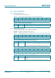
9.3.2.9 RxThresholdReg register
Selects thresholds for the bit decoder.
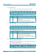
9.3.2.10 DemodReg register
Defines demodulator settings.
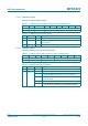
Table 69. RxThresholdReg register (address 18h); reset value: 84h bit allocation
Bit 7 6 5 4 3 2 1 0
Symbol MinLevel[3:0] reserved CollLevel[2:0]
Access R/W - R/W
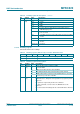
Table 70. RxThresholdReg register bit descriptions
Bit Symbol Description
7 to 4 MinLevel
[3:0]
defines the minimum signal strength at the decoder input that will be
accepted
if the signal strength is below this level it is not evaluated
3 reserved reserved for future use
2 to 0 CollLevel
[2:0]
defines the minimum signal strength at the decoder input that must be
reached by the weaker half-bit of the Manchester encoded signal to
generate a bit-collision relative to the amplitude of the stronger half-bit
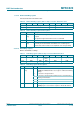
Table 71. DemodReg register (address 19h); reset value: 4Dh bit allocation
Bit 7 6 5 4 3 2 1 0
Symbol AddIQ[1:0] FixIQ TPrescal
Even
TauRcv[1:0] TauSync[1:0]
Access R/W R/W R/W R/W R/W
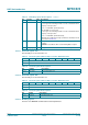
Table 72. DemodReg register bit descriptions
Bit Symbol Value Description
7 to 6 AddIQ
[1:0]
- defines the use of I and Q channel during reception
Remark: the FixIQ bit must be set to logic 0 to enable the following
settings:
00 selects the stronger channel
01 selects the stronger channel and freezes the selected channel
during communication
10 reserved
11 reserved
5 FixIQ 1 if AddIQ[1:0] are set to X0b, the reception is fixed to I channel
if AddIQ[1:0] are set to X1b, the reception is fixed to Q channel