
Data Sheet


MFRC522 All information provided in this document is subject to legal disclaimers. © NXP Semiconductors N.V. 2016. All rights reserved.
Product data sheet
COMPANY PUBLIC
Rev. 3.9 — 27 April 2016
112139 48 of 95
NXP Semiconductors
MFRC522
Standard performance MIFARE and NTAG frontend
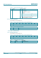
9.3.2.2 ModeReg register
Defines general mode settings for transmitting and receiving.
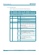
9.3.2.3 TxModeReg register
Defines the data rate during transmission.
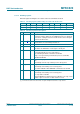
Table 55. ModeReg register (address 11h); reset value: 3Fh bit allocation
Bit 7 6 5 4 3 2 1 0
Symbol MSBFirst reserved TxWaitRF reserved PolMFin reserved CRCPreset[1:0]
Access R/W - R/W - R/W - R/W
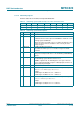
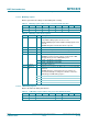
Table 56. ModeReg register bit descriptions
Bit Symbol Value Description
7 MSBFirst 1 CRC coprocessor calculates the CRC with MSB first
in the CRCResultReg register the values for the
CRCResultMSB[7:0] bits and the CRCResultLSB[7:0] bits are bit
reversed
Remark: during RF communication this bit is ignored
6 reserved - reserved for future use
5 TxWaitRF 1 transmitter can only be started if an RF field is generated
4 reserved - reserved for future use
3 PolMFin defines the polarity of pin MFIN
Remark: the internal envelope signal is encoded active LOW,
changing this bit generates a MFinActIRq event
1 polarity of pin MFIN is active HIGH
0 polarity of pin MFIN is active LOW
2 reserved - reserved for future use
1 to 0 CRCPreset
[1:0]
defines the preset value for the CRC coprocessor for the CalcCRC
command
Remark: during any communication, the preset values are
selected automatically according to the definition of bits in the
RxModeReg and TxModeReg registers
00 0000h
01 6363h
10 A671h
11 FFFFh
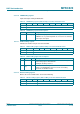
Table 57. TxModeReg register (address 12h); reset value: 00h bit allocation
Bit 7 6 5 4 3 2 1 0
Symbol TxCRCEn TxSpeed[2:0] InvMod reserved
Access R/W D R/W -