
Data Sheet


MFRC522 All information provided in this document is subject to legal disclaimers. © NXP Semiconductors N.V. 2016. All rights reserved.
Product data sheet
COMPANY PUBLIC
Rev. 3.9 — 27 April 2016
112139 43 of 95
NXP Semiconductors
MFRC522
Standard performance MIFARE and NTAG frontend
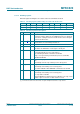
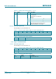
9.3.1.9 Status2Reg register
Contains status bits of the receiver, transmitter and data mode detector.
Table 37. Status2Reg register (address 08h); reset value: 00h bit allocation
Bit 7 6 5 4 3 2 1 0
Symbol TempSensClear I
2
CForceHS reserved MFCrypto1On ModemState[2:0]
Access R/W R/W - D R
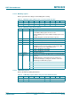
Table 38. Status2Reg register bit descriptions
Bit Symbol Value Description
7 TempSensClear 1 clears the temperature error if the temperature is below the
alarm limit of 125 C
6I
2
CForceHS I
2
C-bus input filter settings:
1the I
2
C-bus input filter is set to the High-speed mode
independent of the I
2
C-bus protocol
0the I
2
C-bus input filter is set to the I
2
C-bus protocol used
5 to 4 reserved - reserved
3 MFCrypto1On - indicates that the MIFARE Crypto1 unit is switched on and
therefore all data communication with the card is encrypted
can only be set to logic 1 by a successful execution of the
MFAuthent command
only valid in Read/Write mode for MIFARE standard cards
this bit is cleared by software
2 to 0 ModemState[2:0] - shows the state of the transmitter and receiver state
machines:
000 idle
001 wait for the BitFramingReg register’s StartSend bit
010 TxWait: wait until RF field is present if the TModeReg
register’s TxWaitRF bit is set to logic 1
the minimum time for TxWait is defined by the TxWaitReg
register
011 transmitting
100 RxWait: wait until RF field is present if the TModeReg
register’s TxWaitRF bit is set to logic 1
the minimum time for RxWait is defined by the
RxWaitReg register
101 wait for data
110 receiving